
The Anatomy of an Arduino Lighter Failure
Building an Arduino lighter—whether you are designing a nichrome wire igniter for a custom gas stove, a solenoid-driven flint striker, or a plasma arc transformer circuit—requires bridging the gap between low-voltage microcontroller logic and high-current physics. When your circuit fails to ignite, the Arduino itself is rarely the culprit. In 2026, with the dominance of 3.3V logic boards like the ESP32 and advanced LiPo batteries, the most common points of failure lie in power delivery mismatches, inductive kickback, and improper gate drive topologies.
This diagnostic guide breaks down the exact failure modes of Arduino-controlled igniter circuits, providing actionable multimeter tests and component-level solutions to get your lighter firing reliably.
1. The Logic-Level MOSFET Trap
The most frequent error in DIY Arduino lighter projects is the "No Heat / No Spark" symptom. You upload the sketch, the GPIO pin goes HIGH, but the nichrome wire remains cold or the plasma arc fails to strike. This is almost always caused by using a standard-power MOSFET instead of a true logic-level MOSFET.
The IRF520 vs. IRLB8721 Mismatch
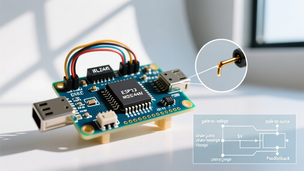
Beginners frequently purchase cheap "MOSFET driver modules" featuring the IRF520. While the IRF520 has a gate threshold voltage (Vgs(th)) of 2.0V to 4.0V, this is merely the voltage at which it begins to conduct. To fully saturate the channel and achieve a low drain-source resistance (Rds(on)), the IRF520 requires a Vgs of 10V. An Arduino Uno outputs 5V, and modern ESP32 boards output only 3.3V. At 3.3V, the IRF520 acts as a massive resistor, dropping voltage, generating extreme heat, and failing to deliver the 3A–5A required to heat 28 AWG nichrome wire to its 1,000°C ignition point.
Expert Fix: Replace the IRF520 with a true logic-level MOSFET like the IRLB8721 or IRLZ44N. The IRLB8721 is specifically characterized for Vgs = 4.5V and will fully saturate even when driven directly by a 3.3V ESP32 GPIO pin, delivering an Rds(on) of just 6.2mΩ.
2. Back-EMF and the "Arduino Reset" Catastrophe
If your Arduino lighter works once, but then the microcontroller immediately reboots, freezes, or the ATmega328P/ESP32 chip becomes hot to the touch, you are experiencing inductive kickback (Back-EMF). This occurs if your lighter mechanism uses a solenoid (for a mechanical flint striker) or a step-up transformer (for a plasma arc).
When you cut power to an inductive load, the collapsing magnetic field generates a massive reverse voltage spike—often exceeding 50V to 100V. This spike travels back through the MOSFET and the power rails, overwhelming the Arduino's voltage regulator and triggering a brownout reset or permanently destroying the silicon. As detailed in All About Circuits' guide to inductive load switching, managing this energy is non-negotiable.
Implementing the Snubber and Flyback Diode
- For DC Solenoids: Solder a 1N4007 flyback diode in reverse bias directly across the solenoid coils (cathode to positive, anode to negative). This provides a safe recirculation path for the collapsing magnetic field.
- For Plasma Arc Transformers: High-frequency AC spikes require an RC snubber network. Place a 100Ω resistor in series with a 0.1µF ceramic capacitor (rated for at least 250V) across the primary coil of your transformer.
3. Power Supply Sag and Battery Chemistry Failures
A nichrome igniter requires a massive, instantaneous burst of current. A standard 9V alkaline battery has an internal resistance of roughly 1.5Ω to 2.0Ω. When the Arduino triggers the MOSFET and attempts to draw 4A, the battery's voltage instantly collapses below 2V, starving both the heater and the microcontroller.
Battery Selection Matrix for Igniter Projects
| Battery Type | Nominal Voltage | Max Continuous Discharge | Verdict for Arduino Lighter |
|---|---|---|---|
| 9V Alkaline | 9.0V | ~100mA - 500mA | FAIL: Severe voltage sag, cannot ignite wire. |
| Standard 18650 Li-ion | 3.7V | 3A - 5A | MARGINAL: Works for short 1-second pulses. |
| High-Drain 18650 (e.g., Sony VTC6) | 3.7V | 15A - 30A | IDEAL: Zero sag, instant orange-hot ignition. |
| 2S LiPo (7.4V) | 7.4V | 20A+ (High C-Rating) | EXCELLENT: Requires PWM to prevent wire melting. |
4. Ground Loops and Optoisolation
When routing high-current paths (4A+) near low-voltage logic paths (5V/3.3V), shared ground traces act as antennas for electrical noise. A voltage drop of just 0.5V across a thin shared ground trace can cause the Arduino's logic to misinterpret LOW/HIGH states or trigger the reset pin.
To diagnose this, measure the voltage between the Arduino's GND pin and the negative terminal of your high-current battery while the igniter is firing. If you see more than 50mV of difference, you have a ground loop.
- Implement Star Grounding: Route the high-current battery ground and the Arduino power ground to a single, thick physical connection point (like a heavy-duty terminal block), rather than daisy-chaining them on a breadboard.
- Use an Optocoupler: For complete electrical isolation, drive the MOSFET gate using a PC817 optocoupler. The Arduino only powers the internal LED (drawing ~10mA, well within the Arduino GPIO absolute maximum limits), while a separate isolated power supply drives the MOSFET gate.
5. Code-Level Diagnostics: Thermal Runaway
If your nichrome wire glows dull orange but fails to ignite the target material, or if it violently melts and snaps after a few uses, your software timing is likely at fault. Nichrome 80 wire (28 AWG) has a positive temperature coefficient; as it heats, its resistance increases. However, continuous DC current will eventually exceed the wire's thermal dissipation limits.
Using the blocking delay() function prevents the Arduino from monitoring safety sensors (like a thermocouple or battery voltage ADC) while the igniter is active. Instead, use a non-blocking millis() approach to pulse the wire, allowing the battery to recover and preventing wire oxidation.
// Non-blocking Arduino Lighter Igniter Pulse Logic
const int MOSFET_PIN = 5;
unsigned long previousMillis = 0;
const long pulseOnTime = 80;   // 80ms ON
const long pulseOffTime = 40;  // 40ms OFF (battery recovery)
bool igniterState = false;

void loop() {
  unsigned long currentMillis = millis();

  if (igniterState == false) {
    if (currentMillis - previousMillis >= pulseOffTime) {
      igniterState = true;
      digitalWrite(MOSFET_PIN, HIGH);
      previousMillis = currentMillis;
    }
  } else {
    if (currentMillis - previousMillis >= pulseOnTime) {
      igniterState = false;
      digitalWrite(MOSFET_PIN, LOW);
      previousMillis = currentMillis;
    }
  }
}
By pulsing the MOSFET at roughly 12Hz with a 66% duty cycle, you maintain the nichrome wire at a brilliant 1,100°C yellow-white heat while reducing average current draw by 34%, drastically extending your battery life and wire longevity. For deeper insights into non-blocking timing architectures, refer to the official Arduino BlinkWithoutDelay documentation.
Summary Diagnostic Checklist
Before tearing down your circuit, run through this rapid diagnostic sequence:
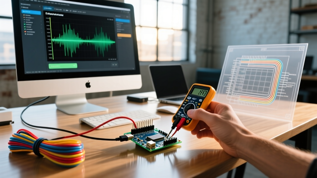
- Multimeter Gate Test: Measure Vgs while the pin is HIGH. If it reads less than 3.0V on an Uno, your GPIO pin is damaged or overloaded.
- Voltage Drop Test: Measure battery voltage at rest vs. during ignition. A drop below 3.2V on a Li-ion indicates a weak cell or undersized wire gauge in your power leads.
- Thermal Camera/IR Thermometer: Check the MOSFET casing. If it exceeds 80°C, you are using the wrong MOSFET or lack a heatsink for continuous operation.
By respecting the physics of high-current resistive and inductive loads, your Arduino lighter projects will transition from frustrating breadboard experiments to reliable, field-ready ignition systems.