
The Core Challenge: Microcontroller Limits vs. Inductive Loads
Building an automated hydroponic doser, a DIY water cooling loop, or an irrigation system requires moving fluids reliably. However, bridging the gap between low-voltage microcontroller logic and high-current fluid dynamics is where most makers destroy their hardware. The fundamental rule of any pump Arduino project is that you must never connect a pump directly to the microcontroller's GPIO pins.
According to the official Arduino Uno Rev3 hardware documentation, the ATmega328P microcontroller has an absolute maximum current rating of 40mA per I/O pin, with a recommended operating limit of just 20mA. A standard 12V DC 385 diaphragm pump—widely used in maker projects for its self-priming capabilities—draws roughly 3.5A under normal load and can spike to 8A or more during startup (stall current). Attempting to drive this directly will instantly vaporize the microcontroller's internal silicon traces.
To solve this, we use the Arduino to switch a secondary, high-current circuit using an intermediary driver component. But which driver is right for your specific fluid control needs?
Choosing the Right Driver for Your Pump Arduino Setup
Selecting the correct switching mechanism depends on your pump's voltage type (AC vs. DC), your need for flow rate modulation, and your project's physical constraints. Below is a comparison matrix of the three most common driver topologies used in 2026 maker projects.
| Driver Type | Best Use Case | Pros | Cons | Approx. Cost |
|---|---|---|---|---|
| Electromechanical Relay | AC water pumps, high-current DC submersibles | Galvanic isolation, handles AC and DC, simple wiring | Mechanical wear, slow switching, no PWM flow control | $2.00 - $4.00 |
| Logic-Level MOSFET | 12V/24V DC diaphragm pumps, peristaltic dosing pumps | Silent, infinite lifespan, supports PWM for precise flow control | DC only, requires heat sinking at high continuous amps | $1.00 - $2.50 |
| H-Bridge / Motor Driver IC | Bi-directional fluid systems, complex robotics | Bi-directional control, built-in overcurrent protection | Overkill for simple on/off pumps, higher cost | $8.00 - $15.00 |
For the vast majority of DC maker applications—such as peristaltic dosing in hydroponics or 12V diaphragm pumps in RV-style water systems—the Logic-Level MOSFET is the superior choice. It allows for Pulse Width Modulation (PWM), enabling you to dial in exact flow rates rather than relying on crude on/off cycling.
The Silent Killer: Inductive Kickback and Flyback Diodes
Water pumps are inductive loads. Inside the motor, coils of wire generate magnetic fields to spin the rotor. When you cut the power via your MOSFET or relay, the magnetic field collapses rapidly. According to Faraday's Law of Induction, this collapsing field induces a massive reverse voltage spike—often exceeding 100V—in a desperate attempt to keep current flowing. This phenomenon is known as inductive kickback or back-EMF.
Without protection, this spike will arc across your relay contacts (causing pitting and welding) or punch straight through the drain-source junction of your MOSFET, permanently shorting it and potentially sending 12V back into your Arduino's ground plane.
Expert Rule: Always place a flyback diode in reverse bias across the pump's terminals. The cathode (stripe) points toward the positive voltage, and the anode points toward the MOSFET drain. For fast-switching PWM applications, use a Schottky diode like the 1N5819 due to its near-zero reverse recovery time. For standard on/off relay circuits, a standard 1N4007 rectifier diode is sufficient. For a deeper dive into diode physics, refer to the SparkFun Diode Guide.
Step-by-Step Wiring: 12V DC Diaphragm Pump via Logic-Level MOSFET
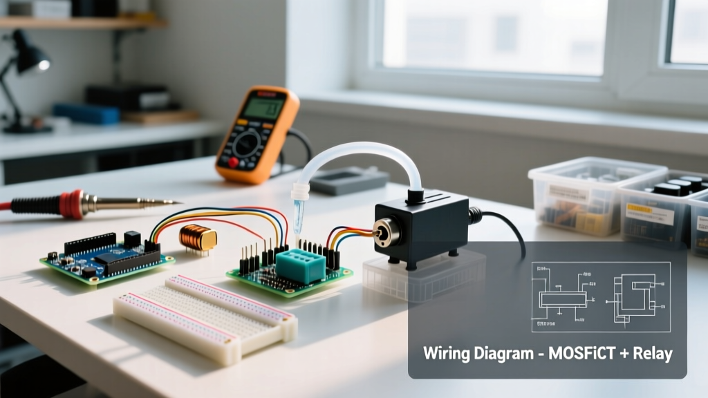
Let's build a robust, PWM-capable circuit for a standard 12V 385 diaphragm pump using an IRLZ44N MOSFET. As of 2026, the IRLZ44N remains a gold standard for hobbyists because it is a true 'logic-level' device, meaning it fully saturates (turns completely on) at the 5V output from an Arduino GPIO pin.
Critical Component Selection and Wiring
- The MOSFET (IRLZ44N): Do not confuse this with the IRF520. The IRF520 is a standard MOSFET requiring 10V+ at the gate to fully open. At 5V, an IRF520 operates in its linear (resistive) region, generating massive heat and failing to deliver full voltage to the pump.
- Gate Resistor (100Ω): Place this between the Arduino PWM pin and the MOSFET gate. It prevents high-frequency parasitic ringing that can cause the MOSFET to oscillate and overheat.
- Pull-Down Resistor (10kΩ): Wire this between the MOSFET gate and ground. When the Arduino boots up, its GPIO pins float in an undefined state. Without this resistor, your pump may stutter or turn on violently during the boot sequence before your sketch initializes.
- Bulk Capacitor (1000µF 25V): Solder this across the 12V and Ground rails near the pump. Diaphragm pumps draw massive current spikes on startup; this capacitor acts as a local energy reservoir to prevent the voltage sag that often causes the Arduino to brownout and reset.
For a comprehensive overview of how these semiconductor switches operate at the silicon level, the SparkFun Transistor Tutorial provides excellent foundational theory.
Non-Blocking Code Architecture for Fluid Control
A common mistake in pump Arduino programming is using the delay() function to time pump run cycles. If you use delay(5000) to run a pump for 5 seconds, the microcontroller is paralyzed. It cannot read soil moisture sensors, monitor water level float switches, or update an LCD screen during that window.
Professional fluid control systems use a non-blocking state machine driven by the millis() function. Below is the conceptual framework for a safe, sensor-driven pump controller:
const int PUMP_PIN = 9; // PWM capable pin
const unsigned long PUMP_RUN_TIME = 3000; // 3 seconds
unsigned long pumpStartTime = 0;
bool pumpIsRunning = false;

void setup() {
  pinMode(PUMP_PIN, OUTPUT);
  digitalWrite(PUMP_PIN, LOW); // Ensure safe state on boot
}

void loop() {
  // 1. Read Sensors (e.g., moisture, float switch)
  bool needsWater = checkMoistureSensor();

  // 2. State Machine Logic
  if (needsWater && !pumpIsRunning) {
    analogWrite(PUMP_PIN, 200); // ~78% duty cycle for soft start
    pumpStartTime = millis();
    pumpIsRunning = true;
  }

  if (pumpIsRunning && (millis() - pumpStartTime >= PUMP_RUN_TIME)) {
    analogWrite(PUMP_PIN, 0); // Cut power
    pumpIsRunning = false;
  }

  // 3. Perform other tasks (update displays, send WiFi data)
}
This architecture ensures the Arduino remains responsive to emergency stop conditions, such as a leak sensor triggering or a reservoir running dry, allowing you to cut power to the pump instantly within the main loop.
Troubleshooting Real-World Pump Arduino Failures
Even with perfect code, physical fluid dynamics and electrical noise introduce edge cases. Here is how to diagnose the three most common pump Arduino failures:
- The 'Brownout Reset' Loop: Your Arduino randomly restarts the moment the pump turns on. Cause: The pump's startup stall current is dragging the shared 12V-to-5V buck converter down below the ATmega328P's 2.7V minimum operating threshold. Fix: Use a dedicated, high-quality switching buck converter (like an LM2596 module rated for 3A) solely for the Arduino, and ensure the 12V power supply is rated for at least 2x the pump's stall current.
- MOSFET Thermal Runaway: The IRLZ44N is too hot to touch after 30 seconds of operation. Cause: You are likely driving a high-impedance load without a proper heatsink, or your gate drive voltage is sagging below 4.5V due to a weak USB power source. Fix: Attach a passive aluminum finned heatsink to the TO-220 package and verify the 5V rail with a multimeter while the circuit is under load.
- Acoustic Whining / Pump Stuttering: The pump emits a high-pitched squeal instead of a smooth hum. Cause: Your PWM frequency is interacting with the pump's mechanical resonance, or the flyback diode is missing/failing, causing micro-arcing. Fix: Verify the flyback diode orientation and use the Arduino
setPwmFrequency()library to shift the PWM carrier frequency outside the audible 20Hz-20kHz range.
By respecting the electrical boundaries of inductive loads and implementing non-blocking, state-aware code, your pump Arduino projects will transition from fragile prototypes to reliable, long-term automation systems.