
The Case for Migrating Away from USB Power
For beginners, powering a microcontroller via a standard USB cable is the path of least resistance. However, as projects evolve from blinking LEDs to driving NEMA 17 stepper motors, cellular IoT shields, or high-brightness LED matrices, USB power becomes a critical bottleneck. Standard USB 2.0 ports cap out at 500mA, and even USB-C PD implementations on newer boards introduce complex negotiation overhead that can fail in headless, remote deployments.
This is where the Arduino VIN (Voltage In) pin becomes essential. Migrating your power architecture from USB or the raw 5V pin to the VIN pin allows you to leverage unregulated external power supplies, battery packs, and industrial DC sources. But this migration is not as simple as plugging in a 12V wall adapter. In 2026, with maker projects increasingly integrating power-hungry edge-AI sensors and wireless telemetry, understanding the thermal and electrical limits of the VIN circuit is mandatory for preventing catastrophic field failures.
Understanding the Physics of the Arduino VIN Pin
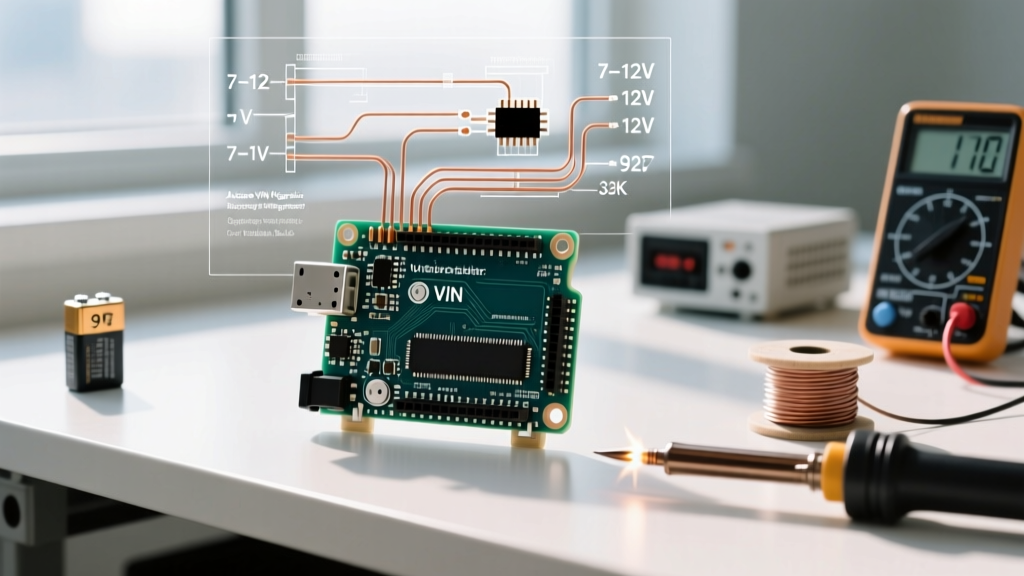
The VIN pin on classic boards like the Uno R3 and Mega 2560 is directly tied to the input of the onboard linear voltage regulator (typically an NCP1117-5.0 in a SOT-223 package). Its purpose is to accept an unregulated voltage and step it down to a clean 5V for the microcontroller and peripherals.
However, linear regulators operate by burning off excess voltage as heat. The power dissipated as heat is calculated using the formula:
P(dissipated) = (V(in) - V(out)) × I(draw)
If you supply 12V to the Arduino VIN pin and your project draws 500mA, the regulator must dissipate (12V - 5V) × 0.5A = 3.5 Watts of heat. The SOT-223 package has a thermal resistance junction-to-ambient of roughly 50°C/W. Without a massive heatsink, a 3.5W dissipation will cause the junction temperature to spike by 175°C above ambient, instantly triggering the regulator's internal thermal shutdown protection. Your board will brown out and reboot continuously.
Power Input Methods Compared
Before executing your migration, review how the Arduino VIN compares to alternative power routing methods on standard development boards.
| Power Method | Voltage Range | Max Current (Safe) | Best Use Case |
|---|---|---|---|
| USB Port | 5V ± 5% | 500mA (USB 2.0) | Desktop prototyping, low-power sensors |
| 5V Pin (Direct) | 4.8V - 5.2V | 1A - 2A (Board dependent) | High-current builds using external buck converters |
| Arduino VIN Pin | 7V - 12V (Rec.) | 300mA (at 12V), 800mA (at 7V) | Battery packs, industrial 12V DC integration |
For a deeper dive into the underlying component physics, the SparkFun tutorial on voltage regulators provides an excellent breakdown of linear versus switching topologies.
Step-by-Step VIN Power Migration Guide
Upgrading to an external power supply via the VIN pin requires careful component selection to ensure long-term reliability. Follow this migration pathway to transition from USB to a robust external DC architecture.
1. Selecting the Right External Power Supply
Avoid cheap, unbranded wall warts that suffer from poor voltage regulation and high ripple. For permanent installations, migrate to enclosed, industrial-grade AC/DC switching power supplies. The Mean Well IRM-10-12 (approx. $16) is a 10W, 12V encapsulated module that provides clean DC output with built-in short-circuit and overload protection. For mobile or off-grid builds, a 3S LiPo battery (11.1V nominal, 12.6V fully charged) paired with a dedicated Battery Management System (BMS) is the gold standard for feeding the Arduino VIN.
2. Wiring and Polarity Protection
When wiring directly to the VIN and GND header pins, reverse polarity is a fatal mistake that will instantly destroy the onboard regulator and potentially the microcontroller. While the DC barrel jack on an Uno R3 includes a built-in P-FET reverse polarity protection circuit, the header pins do not. Always integrate a Schottky diode (like the 1N5819) or an ideal diode controller IC on your external power line before it reaches the VIN header.
3. Managing Voltage Spikes from Inductive Loads
If your 12V supply is shared with inductive loads like relays, solenoids, or DC motors, the back-EMF generated when these components switch off will send high-voltage spikes directly into the Arduino VIN. You must install a flyback diode across the inductive load and add a 100µF electrolytic capacitor paired with a 0.1µF ceramic capacitor directly across the VIN and GND pins on your custom shield to absorb high-frequency transients.
The 2026 Upgrade Path: Bypassing the Linear Regulator
While the Arduino VIN pin is excellent for low-current telemetry nodes, modern maker projects frequently require 5V rails capable of delivering 2A to 5A to support RGB LED strips, servo arrays, or Raspberry Pi compute modules acting as co-processors. Pushing 2A through the onboard linear regulator via the VIN pin is physically impossible without active liquid cooling.
The professional migration strategy is to abandon the Arduino VIN pin entirely for high-current builds and instead use an external switching buck converter to feed the 5V pin directly.
Implementing a High-Efficiency Buck Converter
Instead of routing 12V into the VIN pin, route your 12V source into a high-efficiency step-down (buck) converter. Modules based on the LM2596 (approx. $3) or the more advanced Pololu D36V28F5 (approx. $14, capable of 2.8A continuous) will step the 12V down to 5V with 85-90% efficiency. Because switching regulators store energy in inductors rather than burning it as heat, a 5V/2A draw from a 12V source only draws about 0.9A from the battery, and the module remains cool to the touch.
You then wire the 5V output of the buck converter directly into the Arduino's 5V header pin. This bypasses the onboard NCP1117 entirely. As noted in the official Arduino powering documentation, feeding a regulated 5V source directly into the 5V pin is safe and recommended, provided you never connect a USB cable simultaneously, as this could back-feed power and damage your computer's USB port.
Edge Cases and Troubleshooting the Migration
Even with a meticulously planned power upgrade, real-world physics can introduce edge cases. Keep these troubleshooting insights in mind when debugging your migrated power architecture:
- The 6.1V Drop-Out Trap: The NCP1117-5.0 has a dropout voltage of about 1.1V. If you attempt to power the Arduino VIN with a 6V battery pack (4x AA), the regulator cannot maintain 5V. The board will brown out at around 4.2V, causing erratic behavior and corrupted EEPROM writes. Always ensure your VIN source maintains at least 7V under load.
- USB Back-powering Conflicts: If you leave a USB cable connected for serial debugging while simultaneously powering the board via the VIN pin or 5V pin, you risk back-powering the USB host. While modern boards feature a comparator IC and a MOSFET to auto-switch between USB and VIN power, cheap clone boards often omit this circuitry, leading to fried USB controller chips on your PC.
- Capacitor Inrush Current: When connecting a high-capacity battery to a board with large decoupling capacitors, the inrush current can weld the contacts of your physical switch or trigger the BMS over-current protection. Use a pre-charge resistor or an NTC thermistor in series with the positive lead to limit inrush current during the first 50 milliseconds of connection.
Conclusion
Migrating your project's power source to the Arduino VIN pin is a rite of passage for moving from desktop prototypes to robust, standalone deployments. By respecting the thermal limits of linear regulators, implementing proper transient protection, and knowing when to upgrade to an external buck converter topology, you ensure your microcontroller remains powered reliably in any environment. For further reading on optimizing power delivery for embedded systems, the Pololu voltage regulator guide offers exceptional data on selecting the right switching modules for your specific current requirements.