The Evolution of Arduino CANbus in 2026
As electric vehicles (EVs), advanced robotics, and industrial IoT continue to dominate the maker landscape in 2026, the Controller Area Network (CAN) bus remains the undisputed backbone of robust machine communication. For hobbyists and professional engineers alike, building an Arduino CANbus project is no longer just about reading OBD-II engine codes; it is about reverse-engineering battery management systems (BMS), controlling autonomous rover actuators, and integrating with modern PLCs.
However, the ecosystem is fragmented. Between legacy SPI-based shields, native microcontroller peripherals, and a maze of community-driven libraries, finding the right starting point can be overwhelming. This community resource roundup curates the most reliable hardware configurations, battle-tested libraries, and open-source tools vetted by the electrical engineering and maker communities.
Hardware Matrix: Choosing Your CAN Controller
The days of relying solely on the ATmega328P for CAN communication are behind us. While the classic MCP2515 SPI controller is still widely used, modern 32-bit microcontrollers offer native CAN peripherals that drastically reduce latency and CPU overhead. Below is a comparison of the most popular hardware approaches for Arduino CANbus projects today.
| Hardware Approach | Typical Cost (2026) | Max Baud Rate | Interface | Best Use Case |
|---|---|---|---|---|
| MCP2515 + TJA1050 Module | $2.50 - $4.00 | 1 Mbps (CAN 2.0B) | SPI | Legacy Arduino Uno/Mega, low-speed logging |
| ESP32 Native TWAI | $5.00 - $8.00 | 1 Mbps (CAN 2.0B) | Native GPIO | IoT integration, wireless CAN bridges |
| STM32 (bxCAN / FDCAN) | $4.00 - $12.00 | 5 Mbps (CAN-FD) | Native GPIO | High-speed robotics, EV BMS sniffing |
| MCP2518FD Shield | $15.00 - $25.00 | 8 Mbps (CAN-FD) | SPI | Arduino Due/Teensy CAN-FD networks |
The Great Crystal Oscillator Trap: MCP2515 Pitfalls
If you are using the ubiquitous blue or red MCP2515 modules sourced from Amazon or AliExpress, you must be aware of the crystal oscillator mismatch. This is the single most common failure mode reported in community forums.
- The 16MHz Assumption: Most Arduino CANbus libraries (including the legacy Seeed Studio library) default to a 16MHz SPI clock configuration.
- The 8MHz Reality: Over 70% of cheap clone boards shipped in the last three years use an 8MHz crystal to cut costs and reduce electromagnetic interference (EMI).
- The Symptom: Your code will compile and upload perfectly. The serial monitor will say "CAN Init OK." However, you will receive zero messages, or you will transmit garbage data at exactly half (or double) the intended baud rate.
Expert Fix: Always visually inspect the silver metal can on the MCP2515 board. If it reads '8.000', you must explicitly define
MCP_8MHzin your library initialization. In the Coryjfowler library, this means changingCAN.begin(MCP_ANY, CAN_500KBPS, MCP_16MHZ)toMCP_8MHZ.
Transceiver Selection: 5V vs 3.3V Logic
Another critical hardware decision is the CAN transceiver. The transceiver translates the 3.3V or 5V logic of your microcontroller into the differential voltage of the CANH and CANL bus lines.
- TJA1050: The standard transceiver found on cheap modules. It is strictly a 5V device. If you connect it directly to an ESP32 or Arduino Nano 33 IoT (which operate at 3.3V), you risk damaging the GPIO pins or experiencing erratic bus errors due to logic threshold mismatches.
- TJA1042 / SN65HVD230: These are 3.3V native transceivers. If you are using an ESP32, STM32, or any modern 3.3V Arduino board, you must use a board equipped with one of these transceivers.
- ISO1050 / ADM3053: For automotive or industrial environments where ground loops and voltage spikes are common, community experts strongly recommend using galvanically isolated transceivers. These cost slightly more ($8-$12) but will save your microcontroller when a rogue 12V/24V automotive spike hits the bus.
Top Community-Driven Arduino CANbus Libraries
The software ecosystem for Arduino CANbus has matured significantly. Here are the most trusted libraries maintained by the community as of 2026.
1. Coryjfowler MCP_CAN (The Legacy Standard)
For classic SPI-based MCP2515 and MCP25625 controllers, the MCP_CAN library by Coryjfowler remains the gold standard. It supports custom baud rates, loopback mode, and advanced mask/filter configurations. The community has extensively documented its filter registers, making it the go-to choice for isolating specific OBD-II PIDs from a noisy vehicle bus.
2. ESP-IDF TWAI Driver (The Modern Native Approach)
If you are using an ESP32, abandon SPI adapters entirely. The ESP32 features a native Two-Wire Automotive Interface (TWAI) controller, which is fully compatible with CAN 2.0B. The official Espressif TWAI API provides hardware-level acceptance filtering, alert callbacks, and automatic retransmission. While it requires a slightly steeper learning curve than standard Arduino wrappers, the reduction in CPU interrupts makes it mandatory for high-throughput EV battery sniffing.
3. ACAN2517FD (For CAN-FD Requirements)
As modern vehicles adopt CAN Flexible Data-Rate (CAN-FD) to handle ADAS (Advanced Driver Assistance Systems) and LiDAR data, standard 1Mbps CAN 2.0B is no longer sufficient. The ACAN2517FD library supports the MCP2517FD controller, allowing Arduino-compatible boards like the Teensy 4.1 to transmit payloads up to 64 bytes at speeds up to 8Mbps.
Essential Open-Source Community Tools
Writing Arduino code is only half the battle. To truly master an Arduino CANbus project, you need desktop tools to log, visualize, and reverse-engineer the bus traffic.
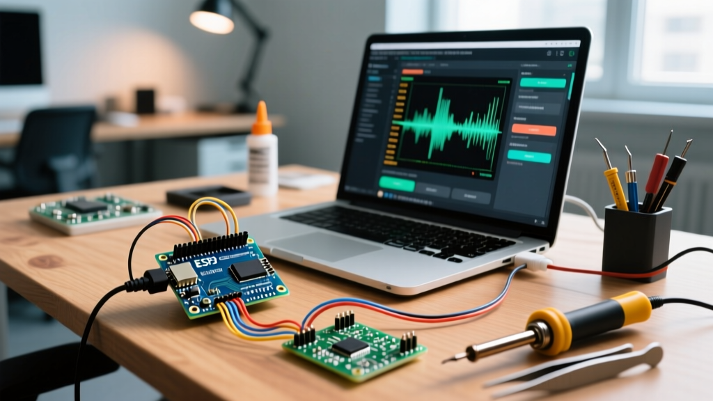
- SavvyCAN: An indispensable open-source tool for reverse engineering. You can use an Arduino or ESP32 as a serial-to-CAN bridge, feeding data into SavvyCAN on your PC. It features automatic DBC file parsing, flow analysis, and fuzzy scope testing to decode unknown vehicle signals.
- Macchina M2: A community-developed, open-source hardware interface that plugs directly into the OBD-II port. It supports multiple CAN channels, SWCAN, and LIN, acting as a bridge between your laptop and the vehicle. The community has built extensive Python and Arduino wrappers for it.
- CanDB++ / DBC Parsers: When working with known vehicle architectures, the community relies on DBC files to map hex payloads to human-readable values (e.g., steering angle, battery SOC). Tools like cantools in Python are frequently paired with Arduino serial loggers to automate this decoding process.
Real-World Troubleshooting: The 120-Ohm Rule
Even with perfect code and verified crystals, physical layer issues will bring your Arduino CANbus network to a halt. The CAN protocol relies on differential signaling and strict impedance matching.
According to the ISO 11898-2 standard, a high-speed CAN bus requires exactly 120 ohms of resistance between CANH and CANL at each physical end of the bus. If you are building a test bench on your desk with just two nodes (e.g., an Arduino Uno and an ESP32), you must ensure that both MCP2515 modules have their termination jumper pins closed. If you measure the resistance between CANH and CANL with a multimeter and read 120 ohms, your bus is unterminated at one end. If you read 60 ohms, your termination is correct. If you read 40 ohms, you have too many termination resistors on the bus, which will cause signal reflection and intermittent 'Error Passive' states in your serial monitor.
Final Thoughts for Makers
The Arduino CANbus ecosystem in 2026 is richer and more capable than ever. By moving away from fragile 5V SPI adapters and embracing native TWAI/FDCAN peripherals, paired with community-vetted tools like SavvyCAN, makers can safely and reliably interface with some of the most complex machines on the planet. Always prioritize galvanic isolation when connecting to live automotive networks, and never trust the silkscreen on a cheap clone module without verifying the crystal oscillator first.