
The Hidden Failures in Fluid Monitoring Projects
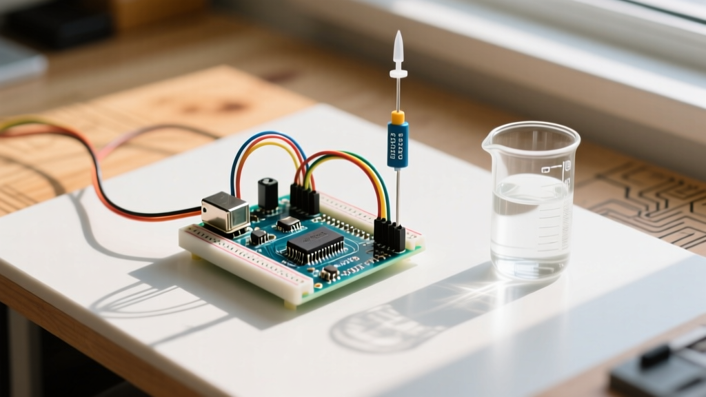
Building a reliable fluid management system is a rite of passage for embedded systems engineers and hobbyists alike. However, when you deploy a water level detection Arduino setup in the real world, laboratory prototypes quickly degrade. Sensors that worked perfectly on a breadboard suddenly return erratic analog values, freeze at zero, or drift wildly. According to the U.S. Geological Survey (USGS), water's universal solvent properties and electrochemical reactivity make it notoriously hostile to exposed electronic components.
This diagnostic guide bypasses basic wiring tutorials and dives straight into the failure modes of the three dominant sensor architectures: resistive, ultrasonic, and capacitive. We will cover exact hardware revisions, specific multimeter diagnostic steps, and firmware-level debugging to restore your system to operational status.
Sensor Architecture & Failure Profile Matrix
Before grabbing a multimeter, identify your sensor topology. Each architecture fails in fundamentally different ways. As of 2026, these are the standard modules and their primary failure vectors:
| Sensor Type | Standard 2026 Model | Avg Cost | Primary Failure Mode | Lifespan in Water |
|---|---|---|---|---|
| Resistive (Trace) | Generic Rain/Water Drop | $1.50 - $3.00 | Galvanic corrosion / Electrolysis | 2 to 8 weeks |
| Ultrasonic | JSN-SR04T (Waterproof) | $8.50 - $12.00 | Acoustic dampening / Logic mismatch | 2 to 5 years |
| Capacitive | FDC2214 Breakout | $14.00 - $18.00 | Parasitic capacitance / Dielectric drift | Indefinite (Non-contact) |
Diagnosing Resistive Sensor Failures: The Electrolysis Trap
The most common water level detection Arduino error occurs when makers leave continuous 5V DC power applied to a resistive trace sensor. When DC current flows through water, it triggers electrolysis. The anode (positive trace) rapidly oxidizes, forming a non-conductive crust of metal oxides and mineral deposits. Within weeks, the sensor reads 'dry' even when fully submerged.
The Pulsed-DC Firmware Fix
To diagnose if electrolysis has occurred, remove the sensor and inspect the traces under a magnifying glass. If you see a dark, pitted, or greenish-black crust on one set of interlocking fingers, the sensor is permanently degraded. To prevent this in future revisions, you must eliminate continuous DC bias.
- Hardware Modification: Do not wire the sensor's VCC directly to the Arduino's 5V rail. Instead, wire VCC to a digital I/O pin (e.g., Pin 8).
- Firmware Execution: Set Pin 8 to
OUTPUTandHIGHonly for the 5 milliseconds required to executeanalogRead(), then immediately set it toLOW. - Advanced Alternative: For high-reliability industrial applications, drive the sensor with an alternating current (AC) using a 555 timer circuit or an H-bridge motor driver to continuously reverse the polarity, nullifying net ion migration.
Stray Voltage and Ground Loop Diagnostics
If your analog readings fluctuate between 200 and 800 when the tank is completely empty, you are likely experiencing a ground loop or stray voltage. Water pipes and pumps often introduce 50/60Hz AC noise into the fluid. Use a true-RMS multimeter to measure the AC voltage between the Arduino's GND pin and the actual fluid in the tank. If the reading exceeds 50mV AC, you must isolate the Arduino's power supply using a DC-DC isolated buck converter (such as the B0505S-1WR3).
Troubleshooting Ultrasonic Sensors (JSN-SR04T)
The JSN-SR04T is the industry standard for waterproof ultrasonic measurement, utilizing a 40kHz acoustic burst. However, it is highly susceptible to environmental and logic-level errors.
The '0 cm' or 'Timeout' Error
When the Serial Monitor outputs a flat 0 or the maximum timeout value (usually 400+), the microcontroller is failing to register the Echo pin's pulse. According to the official Arduino pulseIn() documentation, the function waits for a pin to transition from LOW to HIGH. If this transition never occurs, it times out.
- Logic Level Mismatch: The JSN-SR04T outputs a 5V pulse on the Echo pin. If you are using a 3.3V board (like the Arduino Nano 33 IoT or ESP32), the 5V pulse can trigger internal protection diodes, causing erratic reads or damaging the MCU. Fix: Install a simple voltage divider (e.g., 2kΩ and 3.3kΩ resistors) on the Echo line to step the signal down to a safe 3.1V.
- Insufficient Trigger Pulse: The sensor requires a minimum 10-microsecond HIGH pulse on the Trigger pin. If your sketch uses
delayMicroseconds(5), the sensor will not fire. Increase this to20to ensure reliable triggering across varying cable lengths.
Condensation Blindness
Even 'waterproof' sensors fail in high-humidity environments. When microscopic water droplets form on the acoustic mesh of the transceiver, they scatter the 40kHz sound waves, causing massive signal attenuation. The sensor will report the water level as being much closer than it actually is, or trigger false 'full' alarms.
Expert Tip: Do not wipe the transceiver mesh with a cloth, as this pushes moisture into the acoustic pores. Instead, use compressed air to clear condensation, and apply a hydrophobic nano-coating (like NeverWet or Rust-Oleum LeakSeal) strictly to the outer plastic housing, carefully avoiding the center acoustic membrane.
Capacitive & Non-Contact Sensor Calibration Errors
Capacitive sensing is the gold standard for corrosive or potable liquids because the sensor mounts to the outside of a plastic tank. As detailed in Adafruit's comprehensive guide on capacitive touch sensing, these systems measure changes in the dielectric field. However, they are notoriously prone to parasitic interference.
Dielectric Interference and Parasitic Capacitance
If your capacitive sensor triggers before the water reaches the target height, or fails to trigger at all, the issue is almost always mechanical mounting.
- The Zip-Tie Error: Securing the sensor pad to the tank using nylon zip-ties introduces an inconsistent air gap and variable dielectric material. As ambient humidity changes, the nylon absorbs moisture, altering the parasitic capacitance. Fix: Use double-sided 3M VHB acrylic tape to bond the sensor directly to the tank wall, ensuring a uniform dielectric thickness.
- Tank Wall Thickness: Standard FDC2214 breakout boards are calibrated for acrylic or polypropylene walls between 1.5mm and 3.0mm thick. If your tank is 5mm thick HDPE, the electric field cannot penetrate effectively. You must increase the sensor pad surface area or utilize a sensor with a higher excitation frequency.
Software & Sketch Debugging Matrix
When hardware checks out, the error lies in how the Arduino processes the raw data. Use this diagnostic matrix to map your Serial Monitor output to the underlying software flaw.
| Serial Monitor Symptom | Root Cause | Firmware Correction |
|---|---|---|
| Values jump erratically (e.g., 450, 12, 890, 30) | Missing signal averaging or floating analog pin. | Implement a rolling median filter (take 15 samples, discard highest/lowest 3, average the rest). |
| Readings cap at 1023 regardless of depth. | Incorrect analog reference voltage. | Check analogReference(). If using a 3.3V Pro Mini, ensure VCC is stable; switch to INTERNAL reference for higher resolution. |
| Sensor reads 'Full' when tank is empty. | Inverted logic in threshold mapping. | Resistive sensors read HIGH when wet, LOW when dry. Capacitive sensors often read inversely depending on the oscillator circuit. Invert your map() function. |
| System freezes after 4-5 hours of runtime. | Memory leak from String concatenation. | Replace String objects with char arrays and use snprintf() for serial formatting to prevent heap fragmentation. |
Advanced Diagnostic Workflow: The 4-Step Isolation Protocol
When a deployed system fails in the field, follow this strict isolation protocol to avoid replacing functional hardware:
- Isolate the Transducer: Disconnect the sensor from the Arduino. Use a bench power supply and an oscilloscope (or logic analyzer) to verify the sensor is outputting the correct signal when exposed to water. If the raw signal is clean, the transducer is healthy.
- Verify the Wiring Harness: In wet environments, copper wire wicks moisture via capillary action, leading to hidden corrosion inside the silicone insulation. Perform a continuity test on the harness while physically flexing the cables.
- Test the MCU I/O Pins: Upload a basic blink sketch to toggle the specific analog or digital pins used by the sensor. Measure the pin voltage with a multimeter to ensure the microcontroller's internal pull-up/pull-down resistors or ADC circuits haven't been damaged by a previous voltage spike.
- Deploy a 'Bare-Metal' Sketch: Strip all libraries (like NewPing or OneWire) and third-party code. Write a raw 20-line sketch that only reads the pin and prints to Serial. If the error disappears, the issue is a library conflict or timing interruption caused by other peripherals (like an I2C LCD display blocking the CPU).
By systematically eliminating environmental, hardware, and software variables, you can transform a frustrating water level detection Arduino failure into a predictable engineering solution. Always prioritize non-contact capacitive or properly driven pulsed-DC resistive sensors for long-term deployments, and ensure your logic levels are strictly matched to your microcontroller's architecture.