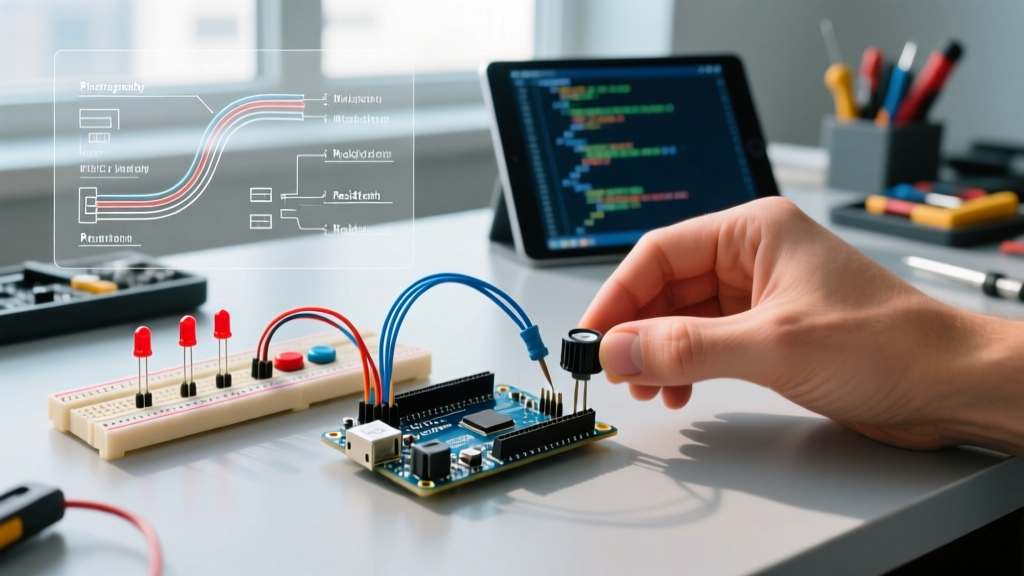

The Architecture of I/O Variables in Modern Arduino
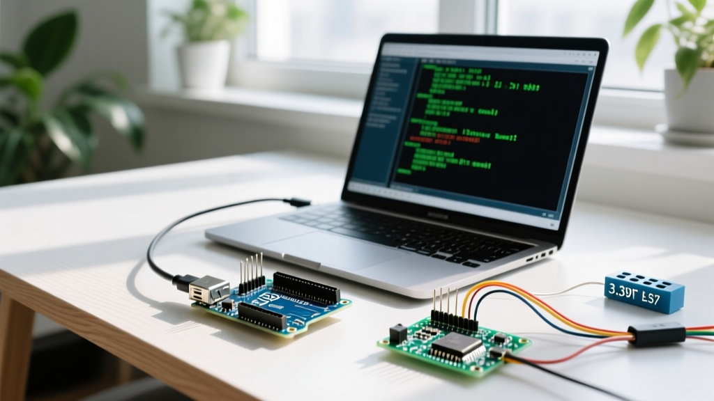
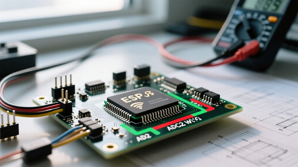
When developing embedded systems, the bridge between the physical world and your microcontroller's logic relies entirely on input and output variables in Arduino sketches. Whether you are reading a 10kΩ thermistor via a voltage divider or driving a 12V MOSFET gate, the software variables storing these states must be flawlessly configured. In 2026, with the widespread adoption of the Arduino Uno R4 Minima (featuring the Renesas RA4M1 ARM Cortex-M4) and the ESP32-S3, the complexity of I/O management has increased. Higher resolution ADCs, faster clock speeds, and stricter C++17 compiler standards in Arduino IDE 2.3+ mean that legacy coding habits often result in silent failures, truncated data, or blocked execution loops.
This troubleshooting guide bypasses basic syntax checks and dives deep into the architectural failure modes of I/O variables. We will diagnose scope shadowing, data type overflow, silent pin mapping mismatches, and polling latency, providing exact technical fixes for each.
Bug #1: Variable Scope and Shadowing (The 'Zero' State Trap)
One of the most pervasive issues when debugging input and output variables in Arduino is variable shadowing. This occurs when a local variable is declared inside a function (like loop() or a custom interrupt service routine) using the same name as a global variable. The compiler prioritizes the local scope, leaving the global variable perpetually uninitialized (usually at 0).
Symptoms
- Sensor readings print correctly inside the function but return
0when accessed by other modules or the main loop. - Output variables fail to trigger actuators because the state update is trapped in a local scope.
The Fix
Never re-declare the data type of a global variable inside your loop. According to the official Arduino variable scope documentation, omitting the type identifier ensures you are updating the existing global memory address rather than allocating a new, temporary one on the stack.
// INCORRECT: Shadows the global variable
int sensorVal;
void loop() {
  int sensorVal = analogRead(A0); // Creates a NEW local variable
}

// CORRECT: Updates the global variable
int sensorVal;
void loop() {
  sensorVal = analogRead(A0); // Updates the global memory address
}Bug #2: Data Type Truncation and Overflow
Microcontrollers process data in strict binary chunks. Assigning a high-resolution sensor input to an undersized variable type results in bitwise truncation, causing erratic actuator behavior. As detailed in the Arduino Data Types Guide, mismatching your variable container to the hardware's output resolution is a critical error.
I/O Variable Matrix: Matching Hardware to Data Types
| Hardware Source | Resolution / Range | Incorrect Type | Correct Type |
|---|---|---|---|
| Uno R3 ADC (Analog In) | 10-bit (0 - 1023) | uint8_t / byte (Max 255) |
int or uint16_t |
| ESP32-S3 ADC | 12-bit (0 - 4095) | int8_t (Max 127) |
uint16_t |
| PWM Output (analogWrite) | 8-bit (0 - 255) | float (Wastes FPU cycles) |
uint8_t / byte |
| Capacitive Touch / Time | Milliseconds (millis) | int (Overflows at 32s) |
unsigned long |
The Fix
Always use fixed-width integer types from the <stdint.h> library (e.g., uint16_t, int32_t) rather than generic int or long declarations. The C++ standard dictates that an int can vary in size depending on the architecture (16-bit on AVR, 32-bit on ARM). Using explicit types ensures your input and output variables in Arduino behave identically whether compiled for an ATmega328P or a Cortex-M4.
Bug #3: Silent Pin Mapping and State Mismatches
Variables often hold the correct logical state, but the physical output fails because the variable is mapped to an incompatible hardware pin. The Arduino API is designed to fail silently in many of these scenarios to prevent runtime crashes, which makes debugging incredibly frustrating.
Common Mismatches
- PWM on Digital-Only Pins: If your output variable calculates a value of
128(50% duty cycle) and you callanalogWrite(2, 128)on an Uno R3, pin 2 will not output a PWM signal. Pin 2 lacks a hardware timer connection. The ATmega328P will default to a high-frequency tone or simply outputHIGHbecause 128 > 0. - Analog Reads on Digital Pins: Calling
analogRead(4)does not read digital pin 4; it reads analog channel 4 (A4). If you intended to read a digital switch on pin 4, your input variable will return floating noise (often ~300-500) instead of a clean0or1.
The Fix
Implement hardware assertion checks in your setup() routine. Create a constant array defining valid PWM pins for your specific board, and write a quick validation function that checks your output variable mappings before the loop() begins. Furthermore, always use the A0, A1 macros for analog inputs to prevent compiler ambiguity.
Bug #4: Polling Latency and Blocking Code
Input variables are only as accurate as their polling rate. If your sketch uses delay() to manage output timing (e.g., blinking an LED or pausing a motor), your input variables are effectively blinded during that window. A 500ms delay means a 10ms button press or a rapid encoder tick will be entirely missed, resulting in an input variable that appears 'stuck'.
The Fix: Non-Blocking State Machines
Replace all temporal delay() functions with millis() based state tracking. This allows the microcontroller to update input variables on every single clock cycle while managing output timing in the background.
unsigned long previousMillis = 0;
const long interval = 1000;
int ledState = LOW;

void loop() {
  // Input variable updates continuously without blocking
  int buttonState = digitalRead(2);

  unsigned long currentMillis = millis();
  if (currentMillis - previousMillis >= interval) {
    previousMillis = currentMillis;
    ledState = !ledState; // Toggle output variable
    digitalWrite(13, ledState);
  }
}
Advanced Diagnostics: When Variables Lie
Sometimes, the software variable is perfectly scoped, correctly typed, and mapped to the right pin, but the physical I/O is still failing. This requires stepping outside the IDE and analyzing the hardware-software boundary.
1. Bypassing the API with Direct Port Manipulation
The standard digitalRead() function takes roughly 3-5 microseconds to execute because it performs pin mapping lookups and disables interrupts. If your input variable requires high-frequency sampling (e.g., reading a 50kHz ultrasonic receiver), the API is too slow. Access the hardware registers directly. For digital pin 2 (PD2 on the Uno R3), read the input variable via the PIN register:
// Reads pin 2 state in a single clock cycle (~62.5 nanoseconds)
bool fastInput = (PIND & (1 << PD2));
For a deeper understanding of C++ scope and hardware registers, refer to the C++ Language Scope Reference, which underpins the Arduino compiler architecture.
2. The ADC Prescaler Bottleneck
By default, the Arduino ADC prescaler is set to 128, resulting in an analog read time of ~104 microseconds. If your input variables are lagging behind a fast-moving analog signal (like an audio waveform), you must lower the prescaler. By manipulating the ADCSRA register in your setup(), you can drop the prescaler to 16, reducing read time to ~13 microseconds, allowing your input variables to capture high-frequency analog data accurately.
Step-by-Step Troubleshooting Checklist
When an I/O variable misbehaves, follow this exact diagnostic sequence to isolate the fault domain:
- Serial Plotter Verification: Open the IDE 2.3+ Serial Plotter (Ctrl+Shift+L). Graph the raw input variable before any math or mapping is applied. If the graph is flat, the issue is hardware (wiring, sensor power). If it is noisy, add a 0.1µF ceramic capacitor between the analog pin and GND.
- Type Casting Check: If using
map(), ensure the output variable is large enough to hold the result.map()returns along; assigning it to abytewithout casting will cause silent rollover errors. - Multimeter Continuity: Set your DMM to continuity mode. Probe the physical pin on the microcontroller header and the sensor output. A variable cannot read a state if the trace is broken.
- ISR Volatility: If the variable is updated inside an
attachInterrupt()function, verify it is declared with thevolatilekeyword. Without it, the compiler's optimization pass will cache the variable in a CPU register, and the main loop will never see the updated hardware state.
Conclusion
Troubleshooting input and output variables in Arduino requires a dual mindset: you must think like a C++ software engineer managing memory scope, and like an electrical engineer understanding hardware limitations. By enforcing strict data typing, eliminating blocking delays, and respecting the physical constraints of the microcontroller's ADC and PWM timers, you can eliminate 99% of I/O bugs in your embedded projects. Always validate your variables at the hardware boundary before blaming the sensor.