
Why Your Arduino Heart Rate Monitor is Failing
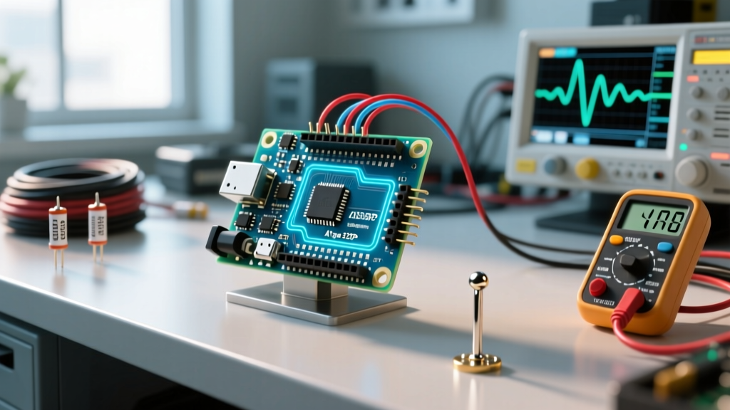
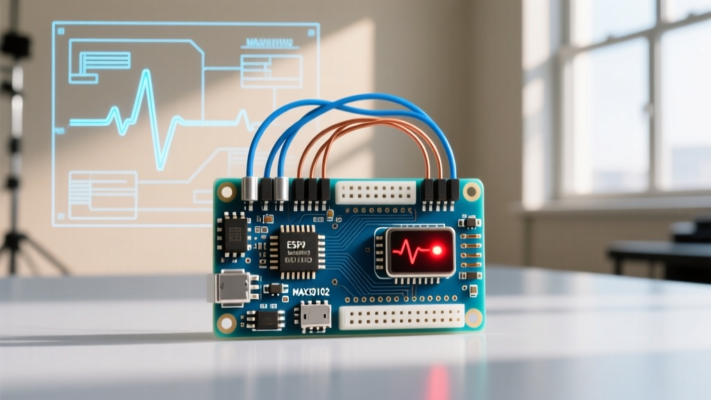
Building an Arduino heart rate monitor is a rite of passage for bio-feedback makers, but the journey from breadboard to reliable BPM (Beats Per Minute) readout is rarely smooth. Whether you are using an analog optical sensor like the PulseSensor Amped or an I2C-based digital IC like the Maxim MAX30102, you will inevitably encounter signal noise, initialization failures, or erratic data spikes. In 2026, while sensor manufacturing has improved, the fundamental physics of photoplethysmography (PPG) remain highly susceptible to ambient light, motion artifacts, and power supply ripple.
This guide bypasses generic advice and dives deep into the electrical and firmware-level troubleshooting required to stabilize your biometric readings. We will cover exact hardware fixes, specific pull-up resistor values, and digital signal processing (DSP) techniques to rescue your project from the 'flatline' of death.
Sensor Architecture Showdown: Analog vs. Digital I2C
Before troubleshooting, you must understand the architectural limitations of your specific sensor module. The fixes for an analog voltage-divider circuit are vastly different from those required for a digital I2C optical array.
| Feature | PulseSensor Amped (Analog) | MAX30102 / MAX30105 (Digital I2C) |
|---|---|---|
| Interface | Analog Voltage (0-5V or 0-3.3V) | I2C (SCL/SDA) |
| Typical 2026 Price | $12.00 - $15.00 (Genuine) | $3.50 - $8.00 (Third-party breakouts) |
| Onboard Processing | None (Hardware op-amp filtering only) | Internal ADC & FIFO Buffer |
| Primary Failure Mode | ADC noise, USB power ripple | I2C NACK, logic level mismatch |
| I2C Address | N/A | 0x57 (7-bit) |
Troubleshooting Analog Sensors (PulseSensor Amped)
The 'Noisy Baseline' and USB Power Ripple
If your Arduino Serial Plotter shows a baseline that looks like a fuzzy caterpillar rather than a clean wave, you are likely experiencing power supply ripple. When powering your Arduino Uno or Nano via a PC USB port, the switching voltage regulators inside the computer's power supply introduce high-frequency noise, which is often compounded by 50Hz/60Hz mains hum coupling into the analog traces.
The Hardware Fix:
- Decouple the Power: Solder a 100nF (0.1µF) ceramic capacitor and a 10µF electrolytic capacitor in parallel across the VCC and GND pins of the PulseSensor. Place them as physically close to the sensor module as possible.
- Isolate the Power Source: Disconnect the USB cable and power the Arduino via the VIN pin using a 9V battery or a clean, regulated LiPo battery shield. If the noise vanishes, your PC's USB ground loop was the culprit.
- Shield the Analog Traces: Analog signals are high-impedance and act as antennas. Keep the wire length between the sensor and the Arduino A0 pin under 6 inches. If you must use longer cables, use a shielded twisted-pair (STP) cable with the shield tied to Arduino GND at only one end to prevent ground loops.
Expert Tip: Never use standard jumper wires for the final analog signal path. The micro-vibrations of cheap Dupont connectors create microphonic noise that the Arduino's 10-bit ADC will interpret as heartbeats. Solder your final analog connections or use screw-terminal shields.
Troubleshooting Digital I2C Sensors (MAX30102 / MAX30105)
I2C Initialization Failures and 'Sensor Not Found' Errors
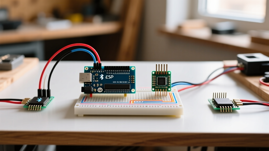
The MAX30102 is an industry-standard PPG sensor, but third-party breakout boards often cut corners on logic level translation. The MAX3010x IC operates strictly at 1.8V internally, with a maximum absolute rating of 3.6V on its I2C pins. If you connect it directly to a 5V Arduino Uno without a proper logic level shifter, you will eventually fry the I2C pull-up resistors or the IC's SDA/SCL diodes, resulting in silent I2C NACK (Not Acknowledged) errors.
Step-by-Step I2C Diagnostic Flow
- Step 1: Run an I2C Scanner. Upload the standard Arduino
I2CScannersketch. If the sensor does not appear at address0x57, proceed to Step 2. - Step 2: Verify Pull-Up Resistors. Most cheap MAX30102 modules include 4.7kΩ pull-up resistors tied to 3.3V. If you are using a 3.3V microcontroller (like an ESP32 or Arduino Nano 33 IoT), this is fine. If you are using a 5V board, you must use a bi-directional logic level converter (like the BSS138 based modules) between the Arduino and the sensor.
- Step 3: Check the INT Pin. Many MAX30102 libraries (such as the popular SparkFun MAX3010x library) require the interrupt (INT) pin to be connected to pull data from the sensor's internal FIFO buffer. If your code hangs during
begin(), ensure the INT pin is wired to a hardware interrupt pin on your Arduino (e.g., Pin 2 on an Uno) and defined correctly in your sketch.
For a comprehensive wiring diagram and library configuration, refer to the SparkFun MAX30105 Hookup Guide, which shares the exact same I2C architecture and firmware logic as the MAX30102.
Combating Motion Artifacts and Ambient Light Bleed
PPG sensors work by shining light into the capillary bed and measuring the refraction. If the sensor shifts by even a millimeter against the skin, the refraction angle changes drastically, causing massive spikes in the data that the algorithm misinterprets as a 200+ BPM heart rate.
Mechanical Stabilization Techniques
Software cannot fix a mechanically unstable sensor. To ensure consistent tissue contact:
- The Velcro Strap Method: Do not rely on your finger pressing the sensor against a breadboard. Use a hook-and-loop strap to secure the sensor firmly to the palmar side of the fingertip or the earlobe. Earlobes are actually superior for PPG because they have dense capillary networks and thinner tissue than fingertips.
- Optical Isolation: Ambient room light (especially 50Hz/60Hz flickering from LED or fluorescent bulbs) will bleed into the photodiode. Build a small 3D-printed shroud or use a piece of heat-shrink tubing over the sensor housing to block external photons. The official PulseSensor documentation heavily emphasizes shielding the sensor from ambient light for accurate analog reads.
Software DSP: Filtering the Signal
Even with perfect hardware, raw PPG data requires digital signal processing. The raw ADC values will contain high-frequency noise and low-frequency baseline wander (caused by respiration).
Implementing a Moving Average and Peak Detection
Instead of relying on basic thresholding, implement a Finite Impulse Response (FIR) filter or a Simple Moving Average (SMA) in your Arduino sketch.
// Example: 4-point SMA for smoothing analog PPG data
int rawValue = analogRead(A0);
smoothedValue = (rawValue + previousValue1 + previousValue2 + previousValue3) / 4;
previousValue3 = previousValue2;
previousValue2 = previousValue1;
previousValue1 = rawValue;
For advanced BPM extraction, utilize the Arduino Analog Read documentation to understand how to optimize the ADC prescaler. By default, the Arduino Uno's ADC clock is set to 125kHz. For high-fidelity PPG sampling, you can manipulate the ADCSRA register to increase the sampling rate, allowing your software filters to operate on a much denser dataset, thereby improving the accuracy of the inter-beat interval (IBI) calculations.
Final Diagnostic Checklist
Before tearing apart your breadboard, run through this definitive checklist:
- Power: Is the sensor powered by a clean, regulated 3.3V source? (MAX30102)
- Logic Levels: Are you using a level shifter if connecting a 3.3V sensor to a 5V Arduino?
- Wiring: Are analog traces under 6 inches and shielded from EMI?
- Optics: Is the sensor shielded from overhead room lighting?
- Mounting: Is the sensor mechanically secured to the skin with consistent pressure?
- Firmware: Is a digital low-pass filter applied before the peak-detection algorithm?
By systematically addressing the electrical, mechanical, and algorithmic layers of your Arduino heart rate monitor, you will transition from erratic, unusable data to clinical-grade biometric tracking. Remember that in bio-sensing, hardware stability always precedes software brilliance.