
The Hidden Costs of Upgrading Your Microcontroller
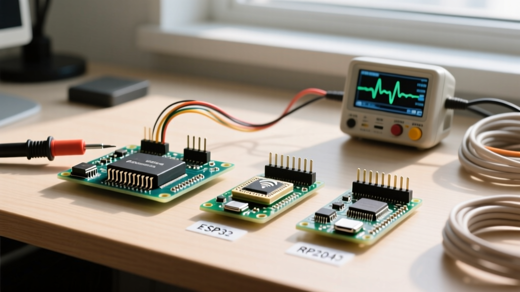
When makers and engineers outgrow the classic Arduino Uno (ATmega328P), the natural progression is migrating to modern powerhouses like the ESP32 or the Raspberry Pi RP2040. These newer microcontrollers offer vastly superior clock speeds, integrated wireless connectivity, and advanced peripherals. However, the physical and electrical realities of upgrading are rarely as simple as swapping out the development board and recompiling your sketch. The most critical point of failure in any MCU migration lies in how you handle the transition of your gpio pins.
A direct drop-in replacement is almost never electrically viable. The ATmega328P operates on a forgiving 5V logic level with robust current sourcing capabilities. In contrast, modern ARM and Xtensa-based MCUs operate on 3.3V logic, feature complex pin multiplexing, and enforce strict boot-strapping requirements. Failing to account for these differences during a migration will result in fried silicon, boot loops, and erratic sensor readings. This guide provides a deep-dive electrical framework for safely migrating your hardware designs to modern architectures.
Voltage Logic Shifts: 5V vs 3.3V GPIO Pins
The most immediate hardware shock during a migration is the logic level voltage drop. The ATmega328P recognizes any voltage above 3.0V as a logical HIGH, and outputs a solid 5V. Modern MCUs like the ESP32 and RP2040 use 3.3V logic. If you connect a 5V output from a legacy sensor or shift register directly into a 3.3V input pin on an ESP32, you will forward-bias the internal ESD protection diodes. This causes excessive current to flow into the VDD rail, potentially lifting the core voltage and destroying the microcontroller.
Conversely, driving a 5V component from a 3.3V gpio pin might not trigger a logical HIGH on the receiving end, as many 5V CMOS chips require at least 3.5V to 4.0V to register a HIGH state. TTL components might accept 3.3V, but relying on this without checking the specific datasheet is a recipe for intermittent noise failures.
Bidirectional Level Shifting Solutions
To safely bridge the 5V and 3.3V domains during a migration, you must implement level shifters. The choice of IC depends heavily on the protocol and speed of your gpio pins:
- MOSFET-Based Shifters (BSS138): Ideal for I2C and low-speed bidirectional communication. They rely on pull-up resistors on both voltage domains. While cheap and ubiquitous on breakout boards, they struggle with high-capacitance loads and frequencies above 400kHz.
- Autodirection Translators (TXS0108E): As detailed in the Texas Instruments TXS0108E datasheet, this IC uses internal 10kΩ pull-ups and edge-rate acceleration circuitry. It is excellent for SPI, UART, and general-purpose bidirectional gpio pins up to 50Mbps, but it can fail if external pull-up resistors are added to the bus, which fights the internal one-shot timers.
- Dedicated Direction Shifters (TXB0104 or 74LVC245): Best for high-speed, unidirectional buses or when you have a dedicated output-enable pin. These provide the cleanest signal integrity for driving WS2812B addressable LEDs or high-speed ADCs.
Navigating Strapping Pins and Boot Failures
Unlike the ATmega328P, where almost every digital pin is available for general use immediately upon power-up, modern MCUs use specific gpio pins to determine the boot mode. These are known as strapping pins. During a migration, if your external circuitry forces a strapping pin into the wrong logic state during the first few milliseconds of power-on, the MCU will enter a serial bootloader, halt execution, or fail to mount its internal flash.
The ESP32 is notorious for this migration hurdle. According to the Espressif Hardware Design Guidelines, several pins are sampled by the internal ROM bootloader upon reset. If you are migrating a relay control circuit or a sensor array, you must actively avoid these pins or implement RC delay circuits to ensure they float to the correct state during boot.
| GPIO Pin | Boot Requirement | Migration Hazard Scenario |
|---|---|---|
| GPIO 0 | Must be HIGH for normal flash boot | Connecting a pull-down button without a hardware debounce or external pull-up resistor causes boot failure. |
| GPIO 2 | Must be LOW or floating | Connecting an active-high LED or a 10k pull-up resistor prevents the chip from entering flash boot mode. |
| GPIO 12 (MTDI) | Determines flash voltage regulator | Pulling HIGH forces 1.8V flash mode, causing brownouts and boot loops on boards with 3.3W SPI flash. |
| GPIO 15 (MTDO) | Controls boot log printing | Pulling LOW silences the bootloader, making UART debugging impossible during firmware migration. |
Failure Mode Alert: A common migration mistake is connecting a 5V I2C OLED display directly to an ESP32 without a level shifter. While the ESP32 might initially read the data, the 5V SDA/SCL lines will slowly degrade the internal ESD protection diodes on the ESP32's gpio pins. Over weeks of operation, this leads to phantom I2C addresses, increased bus capacitance, and eventual silicon failure.
Current Sourcing, Sinking, and Internal Pull-ups
When migrating relay drivers or LED matrices, you must recalculate your current budgets. The ATmega328P allows up to 40mA per pin (with an absolute maximum of 200mA across the entire VCC/GND package). Makers frequently drive small 5V relays directly via a transistor base, or even directly drive low-current LEDs.
Modern MCUs have much stricter limits. The RP2040, as noted in the Raspberry Pi RP2040 Datasheet, has an absolute maximum rating of 50mA for the entire package across all VDD and GPIOIO power domains combined. Driving four gpio pins at 12mA each will push the RP2040 to its thermal and electrical limits, risking voltage sag on the internal 1.1V core regulator. Always migrate to external ULN2003 Darlington arrays or logic-level MOSFETs (like the BSS138 or IRLZ44N) for any load exceeding 8mA per pin.
Furthermore, internal pull-up resistors vary wildly. The ATmega328P features relatively strong 20kΩ to 50kΩ internal pull-ups. The ESP32 and RP2040 typically utilize weaker 45kΩ to 80kΩ pull-ups. If your migrated circuit relies on internal pull-ups for a long cable run or a noisy environment (like a mechanical rotary encoder), the weaker modern pull-ups will result in bouncing and false triggers. Always add external 4.7kΩ or 10kΩ pull-up resistors to critical input gpio pins during a migration.
Remapping Peripherals and Pin Multiplexing
On legacy AVR chips, hardware peripherals like UART, SPI, and I2C are hardwired to specific physical pins (e.g., SPI is strictly on pins 11, 12, and 13 on the Uno). Modern MCUs utilize a GPIO matrix or pin multiplexer, allowing almost any peripheral to be mapped to almost any gpio pin via software.
While this offers immense layout flexibility for custom PCBs, it complicates breadboard migrations. When porting Arduino libraries to the ESP32 or RP2040, hardcoded pin definitions in legacy sketches will fail. You must explicitly define your pin mappings in the setup routine. For example, migrating an SPI SD card module requires updating the SD.begin() function to explicitly pass the new CS, MOSI, MISO, and SCK gpio pin assignments, rather than relying on the default hardware SPI bus definitions of the older IDE cores.
Additionally, beware of input-only pins. The ESP32 features gpio pins 34 through 39 which are physically disconnected from the output driver circuitry. They possess no internal pull-up or pull-down resistors and can only be used for ADC inputs or external interrupts. Attempting to migrate a digital output function to these pins will result in silent failures.
A Step-by-Step Migration Checklist for GPIO Pins
To ensure a robust transition from 5V AVR architectures to 3.3V ARM/Xtensa platforms, run your schematic and code through this final validation checklist:
- Audit Voltage Domains: Highlight every 5V sensor and actuator. Insert BSS138 or TXS0108E level shifters on all data lines crossing the 3.3V/5V boundary.
- Clear Strapping Pins: Cross-reference your chosen gpio pins against the manufacturer's strapping pin table. Move relays, switches, and pull-ups away from GPIO 0, 2, 12, and 15 (ESP32) or QSPI flash pins (RP2040).
- Recalculate Current Draw: Sum the maximum continuous current of all active outputs. Ensure it remains below 80% of the MCU's total package current limit.
- Fortify Input Pull-ups: Replace reliance on internal pull-ups with external 10kΩ resistors on all I2C buses, interrupt lines, and mechanical switches.
- Update Firmware Pin Maps: Remove hardcoded AVR pin assumptions. Explicitly declare SPI, I2C, and UART pin mappings in your initialization code to leverage the modern GPIO matrix.
- Verify Input-Only Restrictions: Ensure no output devices (LEDs, buzzers, relays) are mapped to ADC-only or input-only gpio pins.
By treating gpio pins not just as software variables, but as complex electrical interfaces with strict physical limitations, your upgraded projects will achieve the reliability required for professional and long-term maker deployments.