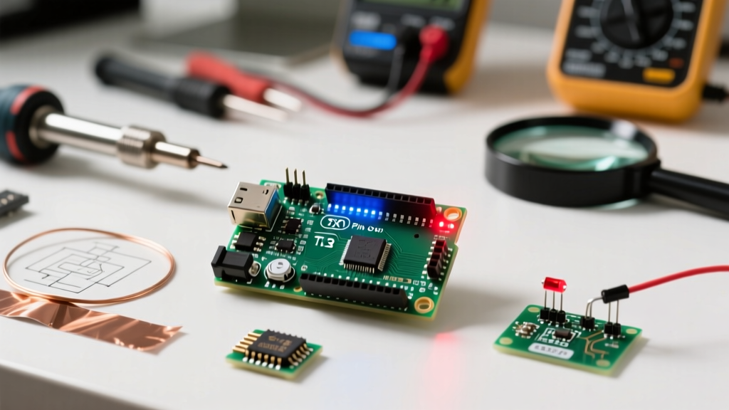

Defining the 'Arduino Light' Problem
When makers and engineers search for an "Arduino light" issue, they are almost always referring to one of two distinct hardware scenarios: the onboard indicator LEDs (Power, Pin 13 'L', TX, and RX) are misbehaving, or a basic external LED breadboard circuit refuses to illuminate. As of 2026, with the widespread adoption of the Arduino Uno R4 Minima and WiFi variants alongside legacy R3 boards and millions of third-party clones, the internal routing and failure modes of these indicator lights have evolved. Troubleshooting requires a systematic approach, moving from power delivery and USB-serial bridge diagnostics down to GPIO pin mapping and basic circuit physics.
Onboard LED Diagnostic Matrix
Before writing a single line of code, you must verify the board's hardware health using the onboard indicators. Below is a diagnostic matrix for the standard Arduino Uno form factor (applicable to R3, R4, and most high-quality clones).
| LED Label | Function & Routing | Normal State | Failure Symptom & Probable Fix |
|---|---|---|---|
| ON (Power) | Tied directly to the 5V rail via a 1kΩ resistor. | Solid Green | Off: Blown polyfuse (PTC) on USB line, or dead 5V voltage regulator. Check USB cable and 5V pin with a DMM. |
| L (Pin 13) | Driven by the main MCU (ATmega328P or RA4M1) via an op-amp buffer. | Blinks on boot, then follows Pin 13 logic. | Dim/Off: Blown op-amp (LMV358), or MCU GPIO damage. Always On: Sketch stuck in HIGH state or bootloader crash. |
| TX / RX | Controlled by the USB-to-Serial bridge (ATmega16U2 or CH340G). | Flickers during serial upload/data. | Off during upload: Failed serial bridge IC, missing drivers (CH340), or broken USB data lines (D+/D-). |
Fixing the Pin 13 'L' LED (The Classic Arduino Light)
The Pin 13 LED is the quintessential "Arduino light," universally used for the Blink sketch. However, its underlying hardware implementation varies wildly between board generations and clones.
Legacy Uno R3 vs. Modern Uno R4
On the classic Uno R3, the 'L' LED is not wired directly to the ATmega328P's PB5 pin (Pin 13). Instead, it passes through an LMV358 operational amplifier acting as a buffer. This design prevents the LED from drawing current away from your external circuit if you use Pin 13 for SPI communication. If the 'L' LED is completely dead but Pin 13 outputs a verified 5V when measured with a multimeter, the SMD LED or the LMV358 chip has likely failed due to reverse voltage spikes or electrostatic discharge (ESD).
On the newer Uno R4 Minima and WiFi boards, the Renesas RA4M1 ARM Cortex-M4 handles the LED routing differently. According to the official Arduino hardware documentation, modern boards maintain backward compatibility in the IDE, but the physical trace routing is optimized for 3.3V logic domains, often utilizing dedicated transistor switches rather than op-amps to isolate the GPIO. If your R4 'L' light fails, it is typically a localized SMD component failure rather than a systemic MCU death.
The Clone Board Caveat (CH340G)
If you are using a sub-$10 clone board from Amazon or AliExpress, the USB-to-Serial bridge is likely a WCH CH340G chip instead of the ATmega16U2. These boards often omit the op-amp buffer for Pin 13 to save $0.15 in manufacturing costs, wiring the LED directly to the MCU. While this makes the board cheaper, it means the LED draws roughly 10-15mA directly from your GPIO pin, slightly reducing the current available for external SPI devices. If the light is dim on a clone, it is usually a sign of a low-quality SMD LED or a marginal solder joint on the MCU pin.
External Arduino Light Circuits: Step-by-Step Troubleshooting
If your onboard lights are functional but your external breadboard "Arduino light" circuit remains dark, follow this strict diagnostic flow to isolate the fault.
- Verify the Breadboard Power Rails: Do not assume your breadboard is continuous. Many modern solderless breadboards have a split power rail in the center (indicated by a broken red/blue line). Use a digital multimeter (DMM) to verify 5V and GND continuity across your specific terminal strips.
- Test the LED with Diode Mode: Remove the LED from the circuit. Set your DMM to the diode test mode (usually indicated by a diode symbol). Place the red probe on the anode (long leg) and black on the cathode (short leg). A healthy red 5mm LED will show a forward voltage drop ($V_f$) of approximately 1.8V to 2.2V and emit a faint glow. If the DMM reads 'OL' (Open Loop) in both directions, the LED is internally fractured and dead.
- Check Resistor Continuity: Current-limiting resistors fail open when subjected to excessive heat or power. Pull the resistor and measure it. A standard 220Ω resistor should read between 215Ω and 225Ω. If it reads infinite, replace it.
- Verify GPIO Output: Disconnect the LED circuit. Upload a simple
digitalWrite(pin, HIGH)sketch. Measure the voltage between the target GPIO pin and the Arduino GND. It must read 4.8V to 5.0V. If it reads 0V or floats around 1.2V, the microcontroller pin is permanently damaged (latched off) due to a previous over-current event.
The Math: Why Your External LED is Blown or Dim
As detailed in SparkFun's comprehensive LED guide, treating an LED like a standard resistive load is the most common beginner mistake. LEDs are non-linear diodes; once the forward voltage threshold is crossed, current spikes exponentially, destroying the silicon die in milliseconds if not limited.
Calculating the Correct Resistor
To properly illuminate an external Arduino light without destroying it or the MCU, you must use Ohm's Law: R = (V_source - V_f) / I_target.
- Red/Orange/Yellow LEDs: Typically have a $V_f$ of 2.0V and a max continuous current of 20mA.
Calculation: (5V - 2.0V) / 0.02A = 150Ω (Use the next standard E12 value up: 180Ω or 220Ω). - Blue/Green/White LEDs: Typically have a $V_f$ of 3.2V.
Calculation: (5V - 3.2V) / 0.02A = 90Ω (Use 100Ω or 120Ω).
CRITICAL HARDWARE WARNING: According to the Arduino Digital Pins primer and the ATmega328P datasheet, the absolute maximum DC current per GPIO pin is 40mA, and the total current for all VCC/GND pins combined must not exceed 200mA. Connecting multiple high-power LEDs directly to GPIO pins without a logic-level MOSFET or transistor array (like the ULN2803) will permanently fry the microcontroller's internal bond wires.
Software & Sketch Verification
Hardware faults account for roughly 70% of Arduino light issues; the remaining 30% are software or configuration errors. If your hardware passes the DMM tests, verify the following in the Arduino IDE (version 2.3+ as of 2026):
- Pin Mapping Mismatches: If you are using an ESP32 or Arduino Nano ESP32, the physical pin numbers printed on the silkscreen do not always match the internal GPIO numbers required by the
digitalWrite()function. Always consult the specific board's pinout diagram. - Missing
pinMode()Declaration: By default, Arduino GPIO pins initialize asINPUT. If you forgetpinMode(LED_PIN, OUTPUT);in yoursetup()loop, the pin will operate in a high-impedance state, providing virtually zero current to your external LED, resulting in a completely dark or imperceptibly dim light. - PWM vs. Digital Pins: If you are using
analogWrite()to dim your Arduino light, ensure you are using a PWM-capable pin (denoted by a~symbol on Uno boards). UsinganalogWrite()on a standard digital pin will simply output a static HIGH or LOW based on whether the duty cycle value is above or below 127.
Frequently Asked Questions
Why is my Arduino Nano 'L' light not working, but the code runs?
Many third-party Arduino Nano clones omit the Pin 13 'L' LED entirely to reduce manufacturing costs and save PCB space. Check the silkscreen on your specific board. If the LED footprint is unpopulated (empty solder pads), the board relies solely on the Power and TX/RX lights for status indication. Your code is likely running perfectly fine.
Can I connect an LED directly to the 5V and GND pins without a resistor?
No. While the Arduino's 5V pin can supply up to 500mA (limited by the USB port or onboard regulator), an LED connected directly to 5V without a current-limiting resistor will draw excessive current, overheat, and pop within seconds. Furthermore, the sudden current spike can trip the resettable PTC polyfuse on the Arduino's USB line, causing the entire board to shut down and disconnect from your PC.
My TX/RX lights flash during upload, but the IDE says 'Upload Failed'. What gives?
Flashing TX/RX lights indicate that the USB-to-Serial bridge is successfully receiving data from your PC. If the upload fails immediately after, the issue lies between the serial bridge and the main MCU. This is often caused by a corrupted bootloader, a mismatched board selection in the IDE (e.g., selecting 'Uno' for a 'Duemilanove' board), or a physical break in the PCB trace connecting the serial bridge's TX pin to the main MCU's RX pin.