
The Legacy Bottleneck: Why Migrate Your Sensor Interface?
For over a decade, the MAX6675 breakout board has been the default bridge for connecting a thermocouple to Arduino projects. It was cheap, required only three digital pins, and got the job done for basic 5V microcontrollers like the Arduino Uno. However, as we move through 2026, the maker landscape has shifted heavily toward 3.3V logic architectures (like the Arduino Nano ESP32, Uno R4 Minima, and Portenta H7). The 5V-only MAX6675 is now a liability, requiring cumbersome logic level shifters and offering a meager 12-bit resolution that limits temperature readings to 0.25°C increments.
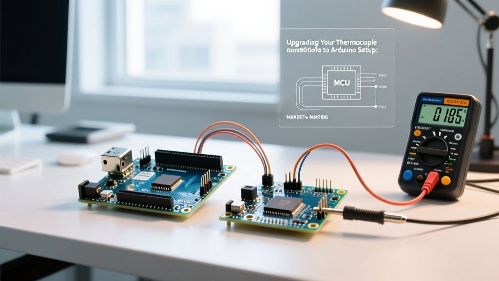
If you are upgrading a legacy kiln controller, CNC plasma cutter, or high-precision reflow oven, migrating to the MAX31856 is not just a convenience—it is a necessity. This guide details the exact hardware, firmware, and electrical engineering steps required to upgrade your thermocouple to Arduino pipeline, eliminating noise, expanding sensor compatibility, and future-proofing your design.
Silicon Showdown: MAX6675 vs. MAX31856 vs. ADS1115
Before ripping out your existing wiring, it is critical to understand the silicon differences. While some engineers attempt to use generic precision ADCs like the ADS1115 with discrete op-amps, dedicated thermocouple-to-digital converters handle Cold Junction Compensation (CJC) and non-linearization internally.
| Feature | MAX6675 (Legacy) | MAX31856 (Modern Upgrade) | ADS1115 + Discrete Amp |
|---|---|---|---|
| Resolution | 12-bit (0.25°C) | 19-bit (0.0078°C) | 16-bit (Depends on gain) |
| Thermocouple Types | K-Type Only | All Standard Types (B, E, J, K, N, R, S, T) | Any (Requires manual math) |
| Logic Voltage | 5V Only | 3.3V and 5V Tolerant | 3.3V / 5V |
| Cold Junction Comp. | Basic Internal | Precision Internal Die Sensor | Requires external IC (e.g., TMP36) |
| Fault Detection | Open Circuit Only | Open, OV/UV, Out of Range | None (Manual implementation) |
| 2026 Avg. Breakout Cost | $8.00 - $12.00 | $14.00 - $19.50 | $10.00 + $4.00 (Amp) |
Hardware Migration: Rewiring the SPI Bus
The MAX6675 utilized a pseudo-SPI 3-wire interface. The MAX31856 uses a true, full-duplex SPI bus. This means your wiring must change to accommodate the Master In Slave Out (MISO) and Master Out Slave In (MOSI) lines, alongside the standard Clock (SCK) and Chip Select (CS).
Step-by-Step Pinout Migration
- VCC & GND: Connect to 3.3V or 5V (the Adafruit and official breakout boards feature onboard regulators and level shifters). Add a 100nF ceramic decoupling capacitor and a 10µF bulk capacitor directly across the VCC/GND pins on the breadboard to suppress high-frequency switching noise.
- SCK (Clock): Route to your MCU's hardware SPI clock pin (e.g., Pin 13 on Uno/Nano, or the dedicated SPI header).
- MISO (Data Out): Route to the MCU's MISO pin (Pin 12). Note: The MAX31856 sends fault data and temperature registers back on this line.
- MOSI (Data In): Route to the MCU's MOSI pin (Pin 11). This is required to write to the MAX31856 configuration registers to set the thermocouple type and noise filtering.
- CS (Chip Select): Use any available digital pin (Pin 10 is standard). Keep this trace as short as possible to prevent capacitive coupling.
Pro-Tip for High-EMI Environments: If your Arduino is mounted near a variable frequency drive (VFD) or induction heater, use a shielded twisted-pair cable for the SPI bus, and ground the shield at the Arduino end only to prevent ground loops.
Firmware Overhaul: Upgrading the Sketch
Migrating your C++ code requires abandoning the legacy max6675.h library. We recommend the Adafruit MAX31856 Library, which abstracts the SPI register mapping and provides built-in fault decoding.
Legacy Code (MAX6675)
#include "max6675.h"
int thermoDO = 12, thermoCS = 10, thermoCLK = 13;
MAX6675 thermocouple(thermoCLK, thermoCS, thermoDO);
void setup() { Serial.begin(9600); }
void loop() {
  Serial.print(thermocouple.readCelsius());
  delay(500);
}
Modernized Code (MAX31856)
The new implementation allows you to define the specific thermocouple metallurgy. According to Fluke's metallurgical guidelines, K-type (Chromel/Alumel) is standard for general purposes, but T-type (Copper/Constantan) is vastly superior for sub-ambient cryogenic measurements. The MAX31856 handles the complex polynomial linearization defined by the NIST ITS-90 Thermocouple Database entirely in hardware.
#include <Adafruit_MAX31856.h>
// Hardware SPI initialization
Adafruit_MAX31856 max31856 = Adafruit_MAX31856(10); // CS Pin

void setup() {
  Serial.begin(115200);
  if (!max31856.begin()) {
    Serial.println("FATAL: MAX31856 SPI Handshake Failed.");
    while (1) delay(10);
  }
  // Configure for K-Type and enable 50Hz/60Hz mains noise rejection
  max31856.setThermocoupleType(MAX31856_TCTYPE_K);
  max31856.setNoiseFilter(MAX31856_NOISE_FILTER_50HZ);
}

void loop() {
  // Read internal Cold Junction and external Thermocouple temps
  float cjTemp = max31856.readCJTemperature();
  float tcTemp = max31856.readThermocoupleTemperature();

  // Check hardware fault registers
  uint8_t fault = max31856.readFault();
  if (fault) {
    if (fault & MAX31856_FAULT_OPEN) Serial.println("FAULT: Open Circuit / Broken Wire");
    if (fault & MAX31856_FAULT_OVUV) Serial.println("FAULT: Over/Under Voltage");
  } else {
    Serial.printf("CJC: %.2f C | Target: %.4f C\n", cjTemp, tcTemp);
  }
  delay(250);
}
Advanced Troubleshooting: Edge Cases & Failure Modes
When upgrading a thermocouple to Arduino interface, engineers frequently encounter three specific failure modes that the legacy MAX6675 masked or ignored. Here is how to diagnose and resolve them in 2026.
1. The Grounded Thermocouple Ground Loop
The Symptom: Readings jump erratically by 10°C to 50°C when the heater element turns on, or the Arduino resets entirely.
The Cause: You are using a grounded thermocouple probe (where the junction is physically welded to the metal sheath). If that sheath touches a grounded metal chassis, and your Arduino is also grounded via USB, a massive ground loop current flows directly through the SPI isolator or MCU ground plane.
The Fix: Switch to an ungrounded thermocouple probe. Alternatively, use an SPI digital isolator IC (like the ISO7741) between the MAX31856 breakout and the Arduino to physically break the electrical continuity while maintaining data transfer.
2. 50Hz/60Hz Mains Interference
The Symptom: The last two decimal places of your temperature reading flutter constantly.
The Cause: The thermocouple wires act as an antenna, picking up electromagnetic interference from nearby AC mains wiring.
The Fix: The MAX31856 features a dedicated hardware notch filter. Ensure max31856.setNoiseFilter(MAX31856_NOISE_FILTER_50HZ); (or 60Hz depending on your regional power grid) is explicitly called in your setup(). Additionally, ensure your thermocouple extension wire is a proper twisted-pair shielded cable, not standard copper hookup wire.
3. Cold Junction Drift on Custom PCBs
The Symptom: Temperature reads 3°C higher than ambient when the Arduino is enclosed in a 3D-printed case.
The Cause: The MAX31856 calculates the final temperature by measuring the ambient temperature of the PCB terminal block (Cold Junction) and adding it to the thermocouple differential. If your Arduino's voltage regulator or a nearby MOSFET dumps heat into the PCB ground plane, the CJC sensor reads the PCB heat, not the ambient room temperature.
The Fix: Thermally isolate the MAX31856 breakout from heat-generating components. Add copper pour keep-outs under the CJC sensor area, and use ventilated enclosures. For extreme precision, mount the MAX31856 on a remote daughterboard connected via a flat flex cable (FFC) away from the MCU's thermal envelope.
Final Migration Checklist
- [ ] Verify MCU logic levels (3.3V vs 5V) and confirm breakout board compatibility.
- [ ] Replace 3-wire pseudo-SPI with 4-wire hardware SPI (MISO, MOSI, SCK, CS).
- [ ] Install 100nF and 10µF decoupling capacitors on the sensor VCC rail.
- [ ] Update firmware to initialize thermocouple type and mains noise filters.
- [ ] Implement fault-register polling to catch open circuits before thermal runaway occurs.
By executing this migration, your thermocouple to Arduino interface will achieve laboratory-grade resolution, natively support exotic sensor alloys like Type S (Platinum/Rhodium), and operate flawlessly on modern 3.3V edge-computing architectures.