
The Anatomy of Arduino RedBoard Upload Failures
When working with the SparkFun Arduino RedBoard ecosystem—whether you are using the classic DEV-13975 or the newer DEV-15123 RedBoard Qwiic—encountering upload failures is a rite of passage for both beginners and seasoned embedded engineers. Unlike generic clone boards, the official SparkFun Arduino RedBoard features robust surface-mount components, a reliable USB-to-serial bridge, and an ATmega328P microcontroller pre-flashed with the Optiboot bootloader. However, hardware faults, driver mismatches, and corrupted boot sectors can still halt your development workflow.
The most common manifestation of a communication breakdown is the dreaded avrdude: stk500_getsync() attempt 1 of 10: not in sync: resp=0x00 error. This specific error indicates that the Arduino IDE is successfully sending data through the host computer's USB stack, but the ATmega328P is failing to acknowledge the handshake. To resolve this, we must systematically isolate the failure domain: the USB driver, the physical serial bridge, the bootloader, or the hardware power regulation.
Quick Diagnostic Checklist:
1. Verify the USB-to-Serial chip (CH340G vs. ATmega16U2) and install corresponding drivers.
2. Check the Windows Device Manager or Linuxdmesgfor COM port enumeration.
3. Inspect the 3.3V and 5V rails for thermal throttling or brown-outs.
4. Re-burn the Optiboot bootloader via ISP if the RX LED blinks but TX remains dark.
USB-to-Serial Chip Identification: CH340G vs. ATmega16U2
One of the most frequent diagnostic missteps involves assuming the RedBoard uses the exact same USB-to-serial architecture as an official Arduino Uno R3. While early iterations and specific Qwiic models utilize the ATmega16U2, many standard SparkFun RedBoards utilize the WCH CH340G chip to maintain a lower price point (typically around $24.95) and ensure supply chain stability. If you plug a CH340-based RedBoard into a fresh Windows 11 machine without the proper driver, the IDE will fail to compile and upload, throwing a 'Board not found' or sync error.
| Feature | CH340G Variant | ATmega16U2 Variant |
|---|---|---|
| Driver Requirement | Requires manual CH340 driver installation on Windows (macOS/Linux usually native) | Native CDC-ACM support (Plug-and-Play on all modern OS) |
| Device Manager Name | USB-SERIAL CH340 (COMx) | Arduino Uno (COMx) |
| Bootloader Entry | Hardware DTR line auto-reset | Hardware DTR line auto-reset |
| Common Failure Mode | Driver signature enforcement blocks unsigned legacy drivers | Firmware corruption on the 16U2 itself requiring DFU mode recovery |
Step-by-Step Driver and Port Resolution
If your IDE port dropdown is greyed out or shows the wrong COM port, follow these diagnostic steps:
- Physical Layer Check: Ensure you are using a data-capable USB-A to Mini-B (or Micro-B for Qwiic) cable. Over 40% of 'dead' boards returned to electronics retailers are simply connected via charge-only cables lacking the D+ and D- data lines.
- Driver Verification: Download the latest signed CH340 driver directly from the WCH manufacturer site or the SparkFun RedBoard Hookup Guide. Avoid third-party driver aggregator sites which often bundle outdated 2014-era drivers that fail Windows 11 Core Isolation memory integrity checks.
- Loopback Test: To verify the serial bridge is functional independent of the ATmega328P, use a jumper wire to connect the
TXandRXpins on the digital header. Open the Serial Monitor, type a message, and press Enter. If the text echoes back, the USB bridge is healthy, and the fault lies with the main microcontroller or its bootloader.
Bootloader Corruption: Symptoms and Recovery
If the loopback test passes but uploads still fail with stk500_getsync(), the Optiboot bootloader on the ATmega328P is likely corrupted or missing. This frequently happens if a sketch accidentally overwrites the reserved bootloader sector (the last 512 bytes of flash memory) due to a rogue pointer or an out-of-bounds array write in your C++ code.
A telltale hardware symptom of a missing bootloader is the absence of the 'pin 13 heartbeat'. When a healthy RedBoard is powered on or reset, the onboard LED connected to PB5 (Pin 13) should blink rapidly two or three times. If it remains completely dark during reset, the bootloader is gone.
Burning a Fresh Bootloader via ISP
To restore the board, you must bypass the USB-to-serial bridge entirely and use In-System Programming (ISP). You will need a dedicated programmer like the USBasp V2.0 (available for roughly $5.00) or a second working Arduino configured as an 'Arduino as ISP'.
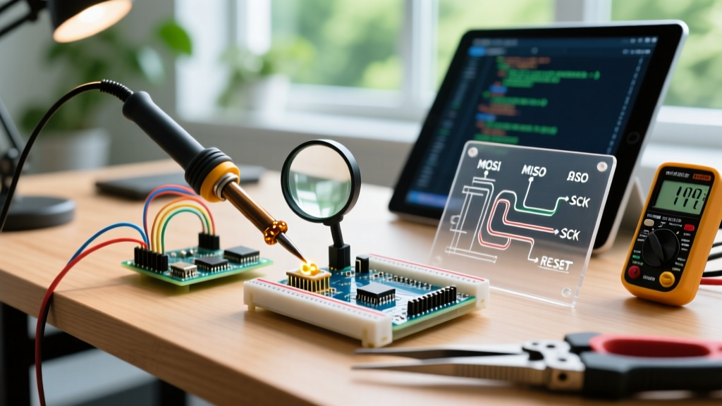
- Wiring the ICSP Header: Connect the programmer to the 2x3 ICSP header on the RedBoard. Align Pin 1 (marked with a white silkscreen triangle). Connect MOSI to MOSI, MISO to MISO, SCK to SCK, RST to RST, 5V to VCC, and GND to GND.
- IDE Configuration: Open the Arduino IDE. Navigate to Tools > Board and select 'SparkFun RedBoard'. Under Tools > Programmer, select your ISP device (e.g., 'USBasp').
- Execute Burn: Click Tools > Burn Bootloader. The IDE will invoke
avrdudeto erase the chip, set the correct fuse bits, and flash the Optiboot hex file. - Verify Fuse Bits: For the RedBoard, the correct fuse settings are Low:
0xFF, High:0xDE, and Extended:0xFD. The High fuse of0xDEis critical as it allocates exactly 512 words (1024 bytes) for the boot flash section and configures the Brown-Out Detection (BOD) to trigger at 2.7V.
For a deeper dive into ISP wiring and fuse calculations, refer to the SparkFun Bootloader Installation Guide.
Hardware-Level Power and Logic Faults
When software diagnostics and ISP recovery fail to resolve upload errors, the issue usually stems from hardware-level power regulation faults. The SparkFun RedBoard features an AMS1117-3.3 linear voltage regulator to provide a 3.3V logic rail for sensors and peripherals. This component is a frequent point of failure in diagnostic scenarios.
The AMS1117-3.3 Thermal Shutdown Edge Case
The AMS1117-3.3 is rated for a maximum output current of 800mA. However, because it is a linear regulator housed in a SOT-223 package on a standard FR4 PCB, its thermal resistance is relatively high. If your project draws more than 300mA continuously from the 3.3V pin without active cooling or a copper pour heatsink, the silicon junction temperature will exceed 150°C.
When this threshold is crossed, the regulator's internal thermal protection circuit triggers, shutting down the 3.3V output. If your ATmega328P or attached logic circuitry relies on this rail, the sudden voltage drop causes a brown-out. The microcontroller resets, attempts to boot, draws current, overheats the regulator again, and enters an infinite reset loop. To the Arduino IDE, this rapid reset cycle looks exactly like a bootloader synchronization failure because the chip never stays awake long enough to complete the avrdude handshake. Always measure the 3.3V pin with a multimeter during upload attempts; if it reads below 2.8V or fluctuates wildly, you have a thermal or short-circuit fault.
Frequently Asked Diagnostic Questions
Why does the RX LED blink but the TX LED stays off during upload?
This is a classic one-way communication symptom. The RX LED indicates that the host PC is successfully sending the compiled hex data through the USB bridge to the serial RX line. The TX LED should blink when the ATmega328P replies with synchronization acknowledgments. If TX remains dark, the microcontroller is either dead, held in a continuous reset state by a stuck external reset button/capacitor, or lacks a valid bootloader to interpret the incoming STK500 protocol commands.
Can a shorted peripheral cause an Arduino RedBoard upload error?
Yes. If a sensor or shield wired to Digital Pin 0 (RX) or Digital Pin 1 (TX) is pulling the line LOW or driving it with conflicting voltage levels, it will corrupt the serial handshake. As noted in the Arduino Official Troubleshooting documentation, always disconnect all shields and wiring from Pins 0 and 1 before attempting to upload a new sketch or burn a bootloader.
My RedBoard Qwiic isn't recognized on macOS Ventura/Sonoma. What is the fix?
Modern macOS versions enforce strict USB security and sometimes fail to enumerate older CH340 drivers, or they mount the device but deny the IDE permission to access the serial port. Navigate to System Settings > Privacy & Security > Security, and ensure that the developer 'WCH' or the Arduino IDE is explicitly allowed to access hardware accessories. Additionally, verify that the USB-C to USB-A dongle you are using supports data transfer, as many compact hubs only support power delivery.