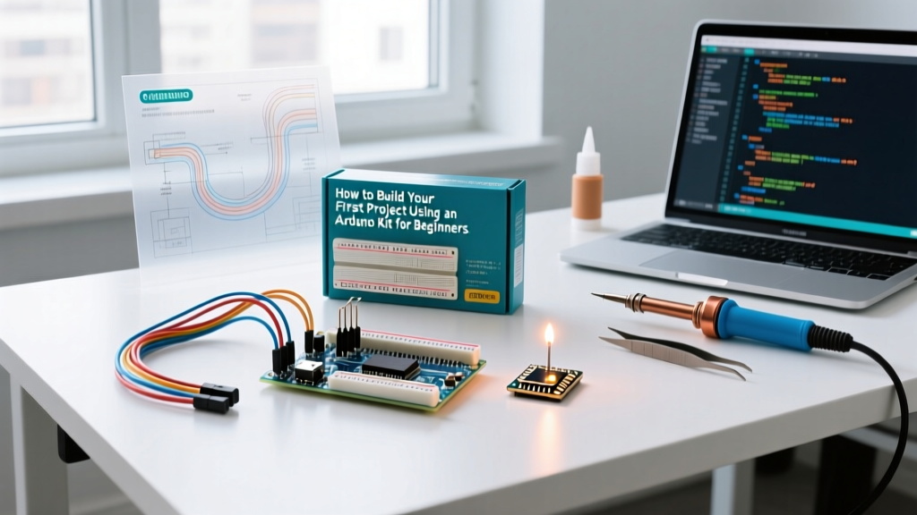

Entering the world of embedded systems in 2026 is more accessible than ever, yet the initial hardware and software hurdles remain a rite of passage. If you have just unboxed an Arduino kit for beginners—likely an UNO R3 clone bundle like the popular Elegoo Super Starter Kit (retailing around $38-$45)—you are holding a microcontroller capable of reading sensors, driving motors, and communicating over serial protocols. However, jumping straight into copying and pasting code without understanding the underlying electronics or software environment is the fastest way to fry a component or abandon the hobby out of frustration.
This tutorial bypasses the generic 'blink an LED' introduction. Instead, we will audit your kit, resolve the most common clone-board driver failures, and build an automated analog night-light using a voltage divider and Ohm's Law. By the end of this guide, you will understand not just how to wire a circuit, but why specific component values are required.
Auditing Your Arduino Kit for Beginners
Most beginner kits contain 200+ components, but only a fraction are used in the first month. Before opening the IDE, verify you have the critical path components and inspect them for common manufacturing traps.
| Component | Specification / Model | Purpose in Starter Projects | Common Beginner Trap |
|---|---|---|---|
| Microcontroller Board | UNO R3 (ATmega328P) w/ CH340G | The brain; processes logic and I/O | Using a 'charge-only' USB cable, resulting in no serial data connection. |
| Solderless Breadboard | 830-point (MB-102) | Prototyping circuits without soldering | Assuming the red/blue power rails are continuous across the center gap. |
| Resistors | 220Ω, 1kΩ, 10kΩ (1/4W) | Current limiting and voltage division | Misreading color bands; confusing 220Ω (Red-Red-Brown) with 2.2kΩ. |
| Photoresistor (LDR) | GL5528 (10-20kΩ at 10 lux) | Ambient light sensing (analog input) | Connecting directly to 5V without a pull-down resistor (creates a short). |
| Jumper Wires | Male-to-Male (22 AWG) | Breadboard connections | Using wires that are too long, creating parasitic capacitance and noise. |
Software Environment and the CH340G Clone Dilemma
Official Arduino boards use the ATmega16U2 chip for USB-to-Serial conversion. However, 90% of third-party Arduino kits for beginners use the CH340G or CH340C chip to keep costs down. While functionally identical for basic sketches, the CH340G requires a specific driver that is not always natively recognized by modern operating systems like Windows 11 or macOS Sonoma/Sequoia.
Resolving 'Port Greyed Out' Errors
If you plug in your UNO R3 clone and the Tools > Port menu in the Arduino IDE is greyed out, your computer is not recognizing the serial interface. Do not blame the board yet.
- Verify the Cable: Swap your USB Type-B cable. Over 40% of 'dead on arrival' beginner boards are actually victims of charge-only cables lacking the internal D+ and D- data wires.
- Install the WCH Driver: Download the official CH340 driver from the chip manufacturer (WCH) or rely on the SparkFun CH340 Driver Installation Guide for verified, malware-free links.
- Check Device Manager: On Windows, look under 'Ports (COM & LPT)'. If you see 'USB-SERIAL CH340' with a yellow warning triangle, you must disable Windows Driver Signature Enforcement temporarily to install the legacy driver, though the latest 2026 WCH signed drivers usually bypass this.
Once the port is visible, ensure you are using the modern Arduino IDE 2.3.x. The legacy 1.8.x IDE is deprecated and lacks the real-time serial plotting and auto-complete features crucial for debugging sensor data.
Project Build: Automated Analog Night-Light
We will build a circuit that reads ambient room light and smoothly fades an LED when the room gets dark. This requires understanding analog inputs, voltage dividers, and pulse-width modulation (PWM).
Step 1: The Math (Voltage Dividers and Current Limiting)
The ATmega328P analog pins (A0-A5) read voltage between 0V and 5V, mapping it to a 10-bit integer (0-1023). A photoresistor changes resistance based on light, but it does not output a voltage on its own. We must pair it with a fixed resistor to create a Voltage Divider.
The Voltage Divider Formula:
V_out = V_in * (R2 / (R1 + R2))
- R1 (Photoresistor): GL5528. Let's assume 10kΩ in dim room light.
- R2 (Fixed Resistor): 10kΩ.
- V_in: 5V from the Arduino.
In dim light, V_out = 5V * (10k / (10k + 10k)) = 2.5V. This perfectly centers our analog reading around 512, giving us maximum resolution for both brighter and darker conditions.
Current Limiting the LED:
Never connect an LED directly to a 5V pin. Standard red LEDs have a forward voltage (Vf) of ~2.0V and a max current of 20mA.
R = (V_source - V_f) / I = (5V - 2.0V) / 0.02A = 150Ω
Since 150Ω is not a standard E12 resistor value, we round up to 220Ω (Red-Red-Brown-Gold) to ensure the LED operates safely at ~13.6mA.
Step 2: Wiring the Breadboard
CRITICAL HARDWARE WARNING: On standard 830-point breadboards, the red and blue power rails on the left and right sides are not electrically connected across the horizontal center gap (usually around row 30). You must use a jumper wire to bridge the top and bottom halves of the power rail, or your ground (GND) will float, resulting in erratic analog readings.
- Connect Arduino 5V to the red power rail and GND to the blue power rail.
- Insert the GL5528 Photoresistor across the center trench. Connect one leg to 5V.
- Connect the other leg of the LDR to Analog Pin A0.
- Insert the 10kΩ Resistor. Connect one leg to the same node as the LDR and A0. Connect the other leg to GND.
- Insert the LED. Connect the Anode (long leg) to Digital Pin 9 (a PWM-capable pin, denoted by a ~ symbol).
- Connect the 220Ω Resistor from the LED Cathode (short leg) to GND.
Step 3: The C++ Sketch
Upload the following code using the Arduino IDE. Note the use of the map() function to invert the logic: as light decreases, the analog reading drops, but we want the LED brightness (PWM) to increase.
// Automated Night-Light Sketch
const int ldrPin = A0;
const int ledPin = 9;

void setup() {
  Serial.begin(9600);
  pinMode(ledPin, OUTPUT);
}

void loop() {
  int lightLevel = analogRead(ldrPin);

  // Map the 0-1023 range to PWM 255-0 (Inverted for night-light logic)
  // Adjust the 300-800 threshold based on your specific room lighting
  int ledBrightness = map(lightLevel, 300, 800, 255, 0);

  // Constrain values to prevent invalid PWM outputs
  ledBrightness = constrain(ledBrightness, 0, 255);

  analogWrite(ledPin, ledBrightness);

  // Debugging output for the Serial Plotter (Ctrl+Shift+L)
  Serial.print('Raw Light: ');
  Serial.print(lightLevel);
  Serial.print(' | PWM Out: ');
  Serial.println(ledBrightness);

  delay(100); // 10Hz sampling rate prevents LED flickering
}
Three Silent Hardware Killers to Avoid
As you progress beyond this initial project, keep these edge cases in mind to protect your microcontroller:
1. Floating Analog Pins
If you run analogRead() on a pin with nothing connected to it, you will get random, jumping values (e.g., 312, 845, 12). This is not a broken board; it is an antenna picking up electromagnetic interference (EMI) from your body and room wiring. Always ensure analog pins are tied to a definitive voltage or GND via a pull-down/pull-up resistor when not in active use.
2. Exceeding the ATmega328P Pin Current Limit
Each I/O pin on the UNO R3 can source or sink a maximum of 20mA (absolute max 40mA, which risks silicon degradation). The total current across the entire VCC/GND package must not exceed 200mA. If your project requires driving high-power components like 12V LED strips or DC motors, you must use a logic-level MOSFET (like the IRLZ44N) or a relay module. Never drive inductive loads directly from an Arduino pin.
3. Back-EMF from Inductive Loads
If you eventually add a relay or a motor to your kit, remember that collapsing magnetic fields generate massive reverse voltage spikes (Back-EMF) that will instantly destroy the ATmega328P's output transistor. Always wire a flyback diode (like a 1N4007) in reverse parallel across any inductive load.
Next Steps: Expanding Your Embedded Knowledge
Once you have mastered analog inputs and PWM outputs with your Arduino kit for beginners, the next logical step is exploring digital communication protocols. Upgrade your skill set by wiring an I2C OLED display (SSD1306) or a BME280 temperature/humidity sensor. These components use only two wires (SDA and SCL) to transmit complex data arrays, introducing you to the Wire.h library and hexadecimal addressing.
Furthermore, as your projects demand more processing power or wireless connectivity, consider migrating from the UNO R3 to the Arduino UNO R4 Minima (featuring a 32-bit Arm Cortex-M4) or the ESP32-DevKitC for native Wi-Fi and Bluetooth capabilities. The foundational C++ logic and circuit theory you practiced today will translate seamlessly to these advanced architectures.