
The Hidden Limits of the Standard Arduino Map Function
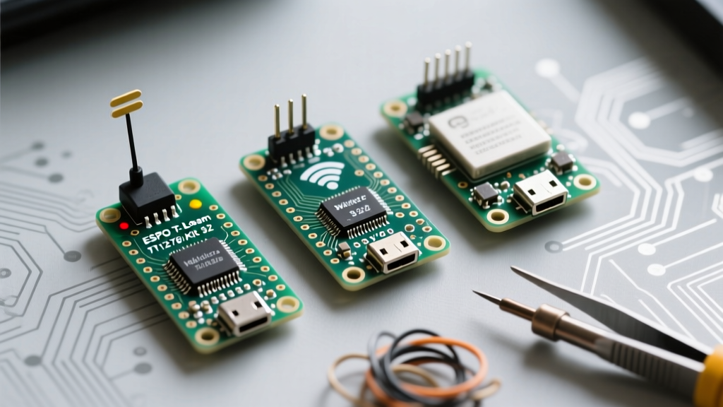
For over a decade, the Arduino map function has been a rite of passage for electronics makers. It provides a simple, one-line solution to scale sensor readings from one range to another. However, as the maker industry transitions heavily toward 32-bit microcontrollers like the ESP32-S3, STM32G4, and Teensy 4.1 in 2026, the mathematical assumptions baked into the legacy 8-bit AVR era are causing silent failures in modern firmware.
When migrating legacy sketches to high-resolution 32-bit architectures, relying on the default Arduino map function often leads to integer overflow, severe truncation errors, and unhandled out-of-bounds exceptions. This migration guide details how to upgrade your mapping logic to match the precision of modern 12-bit and 16-bit analog-to-digital converters (ADCs) and complex non-linear sensors.
The 32-Bit Migration Trap: Silent Integer Overflow
To understand why an upgrade is necessary, we must examine the underlying C++ implementation of the standard function:
long map(long x, long in_min, long in_max, long out_min, long out_max) {
  return (x - in_min) * (out_max - out_min) / (in_max - in_min) + out_min;
}
The function uses 32-bit signed long integers for intermediate calculations. On an Arduino Uno with a 10-bit ADC (0–1023), the maximum intermediate multiplication is relatively small. But consider a modern STM32 or ESP32 setup where you map a 16-bit ADC reading (0–65535) to a high-resolution stepper motor timer register (0–100,000 microsteps).
The intermediate numerator calculation becomes: 65535 * 100000 = 6,553,500,000.
A 32-bit signed long maxes out at 2,147,483,647. The calculation silently overflows, wrapping around into negative numbers and sending completely erratic values to your hardware. This is a catastrophic failure mode that standard unit tests often miss because it only triggers at the upper extremes of the sensor range.
Upgrade Path 1: Floating-Point Precision Mapping (fmap)
Modern 32-bit MCUs feature dedicated hardware Floating Point Units (FPUs). The ESP32-S3 (Xtensa LX7) and Teensy 4.1 (ARM Cortex-M7) execute floating-point math with virtually zero performance penalty compared to integer math. Therefore, the historical aversion to using float or double in microcontroller mapping is obsolete.
Implementing the fmap() Function
To eliminate integer truncation and overflow, migrate your linear scaling to a floating-point equivalent. This is especially critical when mapping to ranges smaller than the input range, where integer division truncates remainders to zero.
double fmap(double x, double in_min, double in_max, double out_min, double out_max) {
  return (x - in_min) * (out_max - out_min) / (in_max - in_min) + out_min;
}
Real-World Application: When calibrating a 12-bit ESP32 ADC (0–4095) to a precise 0.0V–3.3V output display, integer math will yield '0' for any reading below 1248 due to truncation. Using fmap() preserves the fractional voltage data, allowing you to round accurately at the final display stage.
Upgrade Path 2: Piecewise Linear Interpolation for Non-Linear Sensors
The most significant limitation of the Arduino map function is its strict adherence to linear interpolation. Many advanced sensors used in modern robotics and environmental monitoring output highly non-linear data.
- NTC Thermistors: Resistance changes exponentially with temperature.
- Sharp GP2Y0A21YK0F IR Sensors: Voltage output follows an inverse curve relative to distance.
- ESP32 Internal ADCs: As noted in the Espressif ADC documentation, the internal ADC exhibits notable non-linearity, particularly near the 0V and 3.3V saturation rails.
Building a Lookup Table Mapper
Instead of forcing a linear map onto a curved dataset, upgrade to a Piecewise Linear Interpolation function. This approach uses an array of calibrated anchor points and calculates the slope only between the two nearest known data points.
struct MapPoint {
  double input;
  double output;
};

double piecewiseMap(double x, const MapPoint* table, int size) {
  if (x <= table[0].input) return table[0].output;
  if (x >= table[size-1].input) return table[size-1].output;

  for (int i = 1; i < size; i++) {
    if (x <= table[i].input) {
      double slope = (table[i].output - table[i-1].output) /
                     (table[i].input - table[i-1].input);
      return table[i-1].output + slope * (x - table[i-1].input);
    }
  }
  return table[size-1].output;
}
This method requires slightly more SRAM to store the lookup table but guarantees mathematical accuracy for non-linear sensor curves without the heavy CPU overhead of calculating logarithms or exponential functions on the fly.
Migration Comparison Matrix: Which Mapper Fits Your MCU?
| Feature | Standard map() | fmap() (Floating Point) | Piecewise Interpolation |
|---|---|---|---|
| Math Type | 32-bit Signed Integer | 32/64-bit Float/Double | Float/Double with Array Lookup |
| Overflow Risk | High (on 16-bit ADCs) | Negligible | Negligible |
| Non-Linear Support | None | None | Excellent (via calibration) |
| Best Target MCU | Arduino Uno / Nano (8-bit) | ESP32 / STM32 / Teensy | Any MCU with complex sensors |
| Memory Footprint | Minimal (Code only) | Minimal (Code only) | Moderate (Requires SRAM array) |
Critical Edge Cases: Out-of-Bounds and ADC Noise
When upgrading your mapping logic, you must also address the behavioral edge cases that the standard library ignores.
The Missing Clamp Problem
A common misconception is that the Arduino map function constrains values to the output boundaries. It does not. If your input range is 0–1023 and your output range is 0–255, an input of 2000 will return 498, not 255. In motor control or DAC (Digital-to-Analog Converter) applications, this out-of-bounds value can cause hardware damage or undefined behavior.
The Fix: Always wrap your mapping logic with the constrain function, or build clamping directly into your custom fmap or piecewise logic.
// Safe mapping implementation
long safeMap(long x, long in_min, long in_max, long out_min, long out_max) {
  x = constrain(x, in_min, in_max);
  return (x - in_min) * (out_max - out_min) / (in_max - in_min) + out_min;
}
Handling ADC Jitter and Hysteresis
High-resolution 12-bit and 16-bit ADCs are susceptible to electromagnetic interference (EMI), resulting in ±5 to ±15 bits of jitter on the input line. When mapped to a highly sensitive output range, this jitter translates to severe flickering in LEDs or erratic twitching in servos.
Pro-Tip for 2026 Firmware: Never map raw ADC data directly to an actuator. Implement an Exponential Moving Average (EMA) filter or a deadband hysteresis algorithm before passing the value through your mapping function. Mapping amplifies noise; filtering must happen in the raw input domain.
Summary Checklist for Firmware Upgrades
As you migrate your projects from legacy 8-bit development boards to modern 32-bit ecosystems, audit your codebase using this checklist:
- Audit Intermediate Math: Calculate the maximum possible numerator in your standard
map()calls. If it exceeds 2.14 billion, switch tofmap()immediately. - Verify Linearity: Check your sensor datasheets. If the output graph is curved, replace linear mapping with a piecewise lookup table.
- Enforce Boundaries: Ensure every mapping call is paired with
constrain()to prevent out-of-bounds hardware signaling. - Filter Before Mapping: Apply software low-pass filters to raw ADC reads to prevent mapping noise into your control loops.
By retiring the legacy Arduino map function in favor of precision floating-point math and piecewise interpolation, you unlock the true hardware capabilities of modern microcontrollers, ensuring your DIY projects are robust, accurate, and production-ready.