
Introduction to Anemometer Arduino Interfacing
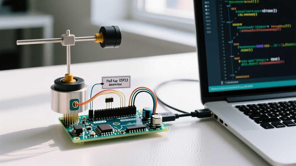
Building a reliable personal weather station or automating a DIY wind turbine requires precise wind speed data. Interfacing an anemometer Arduino setup is a cornerstone project for makers, but moving beyond basic tutorials to achieve meteorological-grade reliability requires understanding hardware interrupts, signal debouncing, and electromagnetic interference (EMI) mitigation. In this comprehensive 2026 guide, we will wire a hall-effect cup anemometer to an Arduino Uno/Nano, write non-blocking interrupt-driven code, and explore the physical siting standards required for accurate readings.
Selecting the Right Wind Speed Sensor
Not all anemometers communicate the same way. Before wiring, you must identify your sensor's output topology. The three most common types in the maker and industrial space are Hall-Effect Pulse, Reed Switch Pulse, and RS485 Modbus RTU.
| Sensor Type | Output Signal | Avg. Cost (2026) | Pros & Cons |
|---|---|---|---|
| Hall-Effect Pulse (e.g., SparkFun SEN-15901) | Digital Square Wave (Hz) | $45 - $60 | Pros: No contact bounce, high RPM capable. Cons: Requires 3.3V/5V power. |
| Reed Switch Pulse (Generic DIY Cups) | Mechanical Contact Closure | $12 - $20 | Pros: Extremely cheap, passive. Cons: Severe contact bounce, fails at high wind speeds. |
| RS485 Modbus (e.g., Renke RS-FS-N01) | Serial (UART via MAX485) | $35 - $50 | Pros: Industrial grade, built-in MCU. Cons: Requires RS485-to-TTL module, complex code. |
For this tutorial, we are focusing on the Hall-Effect Pulse Anemometer. It provides a clean digital signal that perfectly demonstrates how to utilize Arduino hardware interrupts without the mechanical noise of a reed switch.
Hardware Wiring and EMI Protection
A common failure mode in outdoor anemometer Arduino projects is phantom pulse counting caused by EMI. Long cables running from a roof-mounted sensor to an indoor microcontroller act as antennas, picking up radio frequency interference or voltage spikes from nearby solar inverters.
The Pull-Up and Protection Circuit
Hall-effect sensors typically feature an open-collector or open-drain output. This means the sensor can pull the signal line LOW, but it cannot drive it HIGH. You must provide a pull-up resistor.
- VCC (Brown/Red): Connect to Arduino 5V (or 3.3V depending on sensor spec).
- GND (Black): Connect to Arduino GND.
- Signal (Blue/White): Connect to Arduino Digital Pin 2 (INT0).
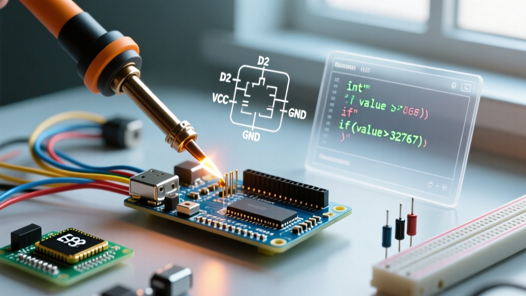
- Pull-Up Resistor: Solder a 10kΩ resistor between the Signal pin and 5V.
- EMI / Debounce Filter: Solder a 100nF (0.1µF) ceramic capacitor between the Signal pin and GND. For extreme environments, add a 5.1V Zener diode or TVS diode (e.g., 1N4148) in parallel to clamp voltage spikes.
Expert Tip: If you are using a mechanical reed switch instead of a hall sensor, the 100nF capacitor is mandatory. Mechanical contacts 'bounce' for milliseconds when closing, which the Arduino will read as dozens of false wind gusts. The capacitor acts as a low-pass hardware debounce filter.
Arduino Code: Hardware Interrupts and Math
To accurately measure wind speed, we cannot use delay() or simple polling loops. If the Arduino is busy writing to an SD card or updating a display, it might miss a pulse from a spinning anemometer. We must use Hardware Interrupts. According to the official Arduino Interrupt Reference, Pin 2 on the Uno/Nano maps to INT0.
Step-by-Step Code Implementation
#include <Arduino.h>

// Pin 2 is INT0 on Arduino Uno/Nano
const byte interruptPin = 2;
volatile unsigned long pulseCount = 0;
unsigned long lastReadTime = 0;
const unsigned long readInterval = 2000; // Read every 2 seconds

// Transfer function: 1 Hz = 2.4 km/h (1.49 mph) for standard SparkFun meter
const float calibrationFactor = 2.4;

void setup() {
  Serial.begin(115200);
  pinMode(interruptPin, INPUT_PULLUP); // Internal pull-up as backup

  // Attach interrupt, trigger on FALLING edge
  attachInterrupt(digitalPinToInterrupt(interruptPin), countPulse, FALLING);
  Serial.println("Anemometer initialized...");
}

void loop() {
  unsigned long currentTime = millis();

  if (currentTime - lastReadTime >= readInterval) {
    // Disable interrupts briefly to safely read the volatile variable
    noInterrupts();
    unsigned long pulsesCopy = pulseCount;
    pulseCount = 0; // Reset for next interval
    interrupts();

    // Calculate Hz (pulses per second)
    float pulsesPerSecond = pulsesCopy / (readInterval / 1000.0);
    float windSpeedKmh = pulsesPerSecond * calibrationFactor;

    Serial.print("Wind Speed: ");
    Serial.print(windSpeedKmh);
    Serial.println(" km/h");

    lastReadTime = currentTime;
  }
}

// Interrupt Service Routine (ISR)
void countPulse() {
  pulseCount++;
}
Code Breakdown and Atomic Reads
Notice the use of the volatile keyword for pulseCount. This tells the compiler that the variable can change unexpectedly inside the ISR, preventing aggressive optimization from caching the value in a CPU register. Furthermore, when reading pulseCount in the main loop, we temporarily disable interrupts using noInterrupts(). This ensures an 'atomic read'—preventing the ISR from firing and altering the count while the main loop is copying the 4-byte long integer.
Calibration and WMO Siting Standards
Even the most perfectly coded anemometer Arduino setup will yield useless data if the sensor is poorly placed. The World Meteorological Organization (WMO) publishes strict guidelines for wind measurement. According to the WMO Guide to Meteorological Instruments, standard wind speed should be measured at exactly 10 meters (33 feet) above ground level in open terrain.
Practical Siting Rules for Makers
- The 10x Rule: The sensor must be placed at a distance of at least 10 times the height of the nearest obstacle. If your house is 5 meters tall, the anemometer should ideally be 50 meters away from it.
- Avoid Roof Vortices: Mounting directly on the peak of a sloped roof causes wind acceleration and turbulence, artificially inflating your wind speed readings by up to 30%.
- Bearing Stiction: Cup anemometers suffer from static friction. Most consumer-grade sensors cannot detect wind speeds below 0.5 m/s. If you require ultra-low wind threshold detection, consider a hot-wire anemometer or an ultrasonic sensor instead.
Troubleshooting Common Anemometer Issues
When deploying your build outdoors, you will inevitably encounter edge cases. Here is how to diagnose them:
- Issue: Wind speed reads impossibly high during thunderstorms.
Cause: Lightning-induced EMI on the cable is triggering the interrupt.
Fix: Install an optocoupler (e.g., PC817) between the anemometer and the Arduino to provide galvanic isolation, and bury the cable in shielded conduit. - Issue: Readings drop to zero at high wind speeds.
Cause: If using a reed switch, the mechanical arm cannot reset fast enough at high RPMs, causing 'missed' pulses.
Fix: Upgrade to a hall-effect sensor which has no moving electrical contacts and can handle frequencies well over 10 kHz. - Issue: Winter freezing.
Cause: Moisture ingress freezes the cup bearings.
Fix: Apply synthetic PTFE grease to the bearings during annual maintenance. Avoid petroleum-based greases which thicken and cause stiction in sub-zero temperatures.
Conclusion
Interfacing an anemometer to an Arduino goes far beyond simple digital reads. By utilizing hardware interrupts, implementing RC low-pass filters for EMI protection, and adhering to WMO siting guidelines, you elevate a basic DIY project into a reliable, long-term meteorological instrument. For further reading on integrating this sensor into a full weather station, check out the SparkFun Weather Meter Hookup Guide for additional rain and wind vane calibration matrices.