
Introduction to DS18B20 and the Arduino Ecosystem
The DS18B20 digital temperature sensor remains one of the most ubiquitous components in the maker and industrial IoT spaces. Utilizing the 1-Wire protocol originally developed by Dallas Semiconductor (later Maxim Integrated, and now Analog Devices), this sensor requires only a single data line to communicate with a microcontroller. However, as the Arduino ecosystem has evolved in 2026—branching into 3.3V ARM Cortex architectures, ESP32-based boards, and the Renesas-powered Uno R4—connecting a DS18B20 to Arduino hardware is no longer a simple plug-and-play affair. Voltage logic mismatches, parasitic power limitations, and bus capacitance issues frequently derail projects. This comprehensive compatibility guide breaks down the exact electrical and software requirements for integrating the DS18B20 across the modern Arduino lineup.
Voltage Logic Compatibility Matrix
The most common point of failure when wiring a DS18B20 to Arduino boards is ignoring logic level thresholds. The 1-Wire protocol relies on precise microsecond timing and specific voltage thresholds to register a logical '1' or '0'. Below is a compatibility matrix for the most popular Arduino boards available today.
| Arduino Board | MCU Architecture | Logic Level | Sensor VCC Requirement | Recommended Pull-Up Resistor |
|---|---|---|---|---|
| Uno R3 / Mega 2560 | 8-bit AVR | 5.0V | 5.0V (External Power) | 4.7kΩ |
| Uno R4 Minima/WiFi | Renesas RA4M1 / ESP32-S3 | 3.3V (5V tolerant I/O) | 3.3V or 5.0V | 3.3kΩ (if 3.3V) / 4.7kΩ (if 5V) |
| Nano ESP32 | ESP32-S3 | 3.3V | 3.3V Strict | 3.3kΩ |
| Zero / Nano 33 IoT | ARM Cortex-M0+ / SAMD21 | 3.3V | 3.3V Strict | 3.3kΩ |
| Portenta H7 | STM32H747 (Dual Core) | 3.3V | 3.3V Strict | 2.2kΩ to 3.3kΩ |
Handling 5V vs 3.3V Logic
When using classic 5V AVR boards, the DS18B20 operates perfectly with a 5V VCC and a standard 4.7kΩ pull-up resistor tied to the 5V rail. However, modern 3.3V boards like the Nano ESP32 or Zero require the VCC pin of the sensor to be connected to the 3.3V output. Supplying 5V to the sensor while reading the data pin with a 3.3V microcontroller can result in degraded signal integrity or, in worst-case scenarios, back-powering the MCU's GPIO pin, potentially damaging the silicon over time. Always match the sensor's VCC to the microcontroller's native logic level.
Wiring Topologies: External vs. Parasitic Power
The DS18B20 supports two distinct power modes. Choosing the wrong mode for your specific application is a primary cause of bus timeouts and CRC (Cyclic Redundancy Check) errors.
1. External Power Mode (Recommended)
In external power mode, the sensor's VDD pin is connected to the microcontroller's voltage rail (3.3V or 5V), GND is connected to ground, and the DQ (data) pin is connected to the GPIO with a pull-up resistor. This mode provides the sensor with ample current to perform analog-to-digital conversions reliably, even at the maximum 12-bit resolution.
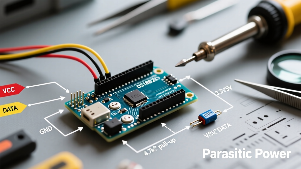
2. Parasitic Power Mode
Parasitic power mode eliminates the need for a dedicated VCC wire by connecting the VDD pin directly to GND. The sensor harvests power directly from the data line via an internal capacitor when the line is pulled high. While this reduces cable complexity (allowing 2-wire waterproof probes), it is highly restrictive.
Expert Warning: Parasitic power mode requires the microcontroller to provide a strong, active pull-up (MOSFET-driven) during the temperature conversion phase to supply the necessary 1.5mA of current. Standard internal pull-up resistors (usually 20kΩ-50kΩ) cannot supply this current. Furthermore, cable runs exceeding 3 meters introduce too much parasitic capacitance, causing the voltage to droop and the sensor to reset mid-conversion, yielding the infamous default '85°C' power-on error.
The Pull-Up Resistor: Sizing for Cable Length and Capacitance
The 1-Wire bus is an open-drain architecture. The microcontroller pulls the line low to transmit, but relies on a physical resistor to pull the line high. The value of this resistor dictates the RC (resistor-capacitor) rise time of the signal. If the rise time is too slow, the microcontroller will misinterpret the timing slots, leading to data corruption.
- Standard Bench Setup (< 1 meter): Use a 4.7kΩ resistor for 5V logic, or a 3.3kΩ resistor for 3.3V logic. This provides a fast rise time while keeping current draw within the GPIO's sinking limits.
- Medium Runs (1 to 5 meters): Drop the resistance to 2.2kΩ or 3.3kΩ to overcome the added capacitance of the copper wire. Ensure your MCU GPIO can safely sink the increased current (approx. 1.5mA at 3.3V with 2.2kΩ, well within the 7mA limit of most modern ARM/ESP32 pins).
- Long Runs / Multiple Sensors (5+ meters or >5 sensors): A passive resistor is no longer sufficient. You must implement an active pull-up circuit using a P-channel MOSFET driven by a secondary GPIO pin, or use a dedicated 1-Wire master IC like the DS2482-100, which handles the complex timing and active pull-up requirements natively.
The Counterfeit Sensor Epidemic: 2026 Market Realities
When sourcing components, hardware engineers must be acutely aware of the counterfeit DS18B20 market. Genuine Analog Devices (formerly Maxim) DS18B20+ sensors in the TO-92 package typically cost between $3.50 and $4.50 each through authorized distributors like Mouser or DigiKey. Conversely, unbranded clones found on bulk e-commerce platforms often sell for $0.50 to $0.80.
These clones frequently suffer from severe edge-case failures:
- The 85°C Bug: The sensor's power-on default register value is 85°C. Genuine chips overwrite this upon successful conversion. Clones often fail to overwrite it under slight voltage sags, reporting 85°C continuously.
- -127°C Errors: Cheap clones fail the internal CRC check when queried rapidly, causing the OneWire library to return a disconnected or error state (-127°C).
- Thermal Drift: Independent teardowns reveal that clone silicon exhibits a ±2.0°C variance across the -10°C to +85°C range, entirely defeating the sensor's advertised ±0.5°C accuracy.
For any deployment where data integrity matters—such as incubators, server rack monitoring, or homebrew fermentation—always source genuine Analog Devices silicon or consider the modern MAX31820 drop-in replacement, which offers improved EMI immunity.
Software Compatibility: OneWire & DallasTemperature
Interfacing the hardware is only half the battle. The software ecosystem for the DS18B20 relies heavily on two foundational libraries: the low-level OneWire library (maintained by PJRC) and the higher-level DallasTemperature wrapper.
Handling the 750ms Conversion Delay
At maximum 12-bit resolution, the DS18B20 requires up to 750 milliseconds to complete a temperature conversion. The default requestTemperatures() function in the DallasTemperature library is blocking, meaning it halts your Arduino's main loop for nearly a full second. In 2026, with most makers running asynchronous web servers, MQTT clients, or RTOS tasks on ESP32s, a 750ms blocking delay is unacceptable.
To resolve this, utilize the non-blocking approach:
#include <OneWire.h>
#include <DallasTemperature.h>

OneWire oneWire(2);
DallasTemperature sensors(&oneWire);

void setup() {
  sensors.begin();
  // Disable blocking waits
  sensors.setWaitForConversion(false);
  sensors.requestTemperatures(); // Initiate first conversion
}

void loop() {
  // Check if conversion is done based on timer or resolution
  float tempC = sensors.getTempCByIndex(0);
  if (tempC != DEVICE_DISCONNECTED_C) {
    // Process valid temperature
  }
  // Request next reading asynchronously
  sensors.requestTemperatures();

  // Main loop continues without blocking
}
Common Failure Modes and Troubleshooting
Even with perfect wiring, environmental and architectural factors can disrupt the 1-Wire bus. Use this diagnostic checklist when your DS18B20 returns DEVICE_DISCONNECTED or erratic values.
- Ghost Addresses: If the ROM search algorithm returns dozens of random, changing addresses, your bus is suffering from signal reflections. Lower the pull-up resistor value or add a small ferrite bead near the sensor's data pin to dampen high-frequency ringing.
- CRC Check Failures: The DallasTemperature library performs a mathematical CRC check on the 8-byte data packet. If the bus is routed near high-current AC lines or switching power supplies, EMI will flip bits in transit. Use shielded twisted-pair cable (like CAT5e) with the shield tied to GND at the microcontroller end only.
- Address Collisions: Every DS18B20 has a factory-lasered 64-bit unique ROM. However, if you are using parasitic power mode and the voltage drops during the ROM read phase, multiple sensors may attempt to drive the bus low simultaneously, causing a short circuit condition on the data line. Always default to external power for multi-drop buses.
Summary
Successfully connecting a DS18B20 to Arduino hardware requires moving beyond basic breadboard tutorials. By matching your pull-up resistor to your board's native logic voltage, avoiding the pitfalls of parasitic power on long runs, and implementing non-blocking library calls, you can build robust, industrial-grade temperature monitoring networks. Always prioritize genuine silicon to ensure the ±0.5°C accuracy and long-term reliability your projects demand.