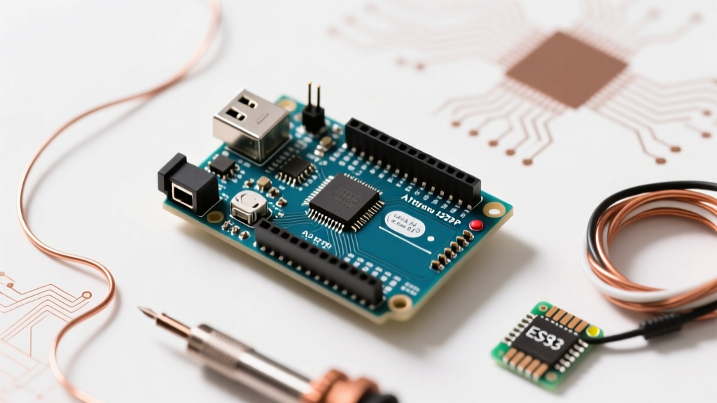

Even as advanced 32-bit microcontrollers and AI-capable edge devices dominate the headlines in 2026, the Uno R3 board for Arduino remains the undisputed workhorse of the maker community, robotics labs, and rapid prototyping environments. Its 5V logic, robust DIP-28 socketed architecture, and massive ecosystem of shields make it an enduring standard.
Whether you are debugging a stubborn upload error, designing a custom shield, or trying to understand the thermal limits of the onboard voltage regulator, this comprehensive FAQ and quick reference guide provides the exact specifications, failure modes, and engineering insights you need.
Core Hardware Specifications & Architecture
At the heart of the Uno R3 is the Microchip ATmega328P-PU, an 8-bit AVR microcontroller. Below is the quick-reference matrix for the board's physical and logical limits.
| Parameter | Specification | Engineering Notes & Limits |
|---|---|---|
| Microcontroller | ATmega328P-PU (DIP-28) | Socketed; can be removed and programmed standalone. |
| Operating Voltage | 5V DC | Logic HIGH threshold is ~3.0V; LOW is ~1.5V. |
| Input Voltage (Rec.) | 7V to 12V | Via barrel jack or VIN pin. |
| Input Voltage (Max) | 20V (Absolute) | Exceeding 12V causes severe LDO thermal throttling. |
| Flash Memory | 32 KB | 0.5 KB used by Optiboot bootloader. |
| SRAM | 2 KB | Volatile memory for variables and stack. |
| EEPROM | 1 KB | Non-volatile; rated for 100,000 write cycles. |
| Clock Speed | 16 MHz | External quartz crystal oscillator. |
Power Architecture: Thermal Limits & Edge Cases
One of the most common hardware failure modes for beginners involves the Uno R3's power regulation circuit. Understanding how to properly power the board is critical for project longevity.
The Barrel Jack and Linear Regulator
The board features an NCP1117ST50T3G (or equivalent) 5V linear voltage regulator. Unlike switching buck converters, linear regulators dissipate excess voltage as heat. The formula for power dissipation is P = (V_in - 5V) × I_load.
Thermal Shutdown Warning: If you supply 12V via the barrel jack and draw just 200mA from the 5V pin to power sensors, the regulator must dissipate 1.4W of heat. The SOT-223 package lacks a heatsink and will hit its internal 125°C thermal shutdown limit within minutes. Rule of thumb: If drawing over 100mA from the 5V pin, keep the barrel jack input voltage at 7V to 8V, or use an external switching buck converter.
USB Polyfuse Reset Times
The USB power line is protected by a resettable PTC polyfuse rated for 500mA. If your sketch or attached shield pulls more than 500mA, the fuse trips, cutting power to protect your host computer's USB port. Note: This fuse requires 10 to 20 minutes to cool down and reset. If your board suddenly dies and won't turn back on, unplug it and wait 15 minutes before assuming the board is dead.
Pinout Quick Reference Card
When wiring sensors or designing shields, keep this communication protocol mapping handy:
- I2C (Wire): SDA (A4), SCL (A5). Note that the R3 revision added dedicated SDA/SCL headers next to the AREF pin for shield compatibility, but they are electrically identical to A4/A5.
- SPI: MOSI (Pin 11), MISO (Pin 12), SCK (Pin 13), SS (Pin 10). Also broken out on the 2x3 ICSP header.
- UART (Serial): TX (Pin 1), RX (Pin 0). Tied directly to the USB-to-Serial bridge. Disconnect devices on pins 0/1 when uploading sketches to avoid data collisions.
- External Interrupts: INT0 (Pin 2), INT1 (Pin 3). Essential for high-speed rotary encoders or hardware-triggered events.
- PWM Capable: Pins 3, 5, 6, 9, 10, and 11 (marked with a ~ on the silkscreen).
Troubleshooting IDE & Upload Errors
Upload failures are the most frequent roadblock when working with the Uno R3 board for Arduino. Here is how to diagnose the exact point of failure in the Arduino IDE 2.x environment.
Error: 'avrdude: ser_open(): can't open device'
Cause: The IDE cannot establish a serial connection to the COM port. This is almost exclusively a driver or port selection issue.
- Open the IDE and navigate to Tools > Port. Ensure the correct COM port (Windows) or /dev/tty.usbmodem (macOS) is selected.
- If the port is greyed out or missing, you are likely using a clone board with a WCH CH340 USB-to-Serial chip. You must manually install the CH340 drivers from a trusted source and restart your machine.
- Check your physical USB cable. Over 30% of 'dead' boards are simply connected via charge-only cables lacking the D+ and D- data lines.
Error: 'avrdude: stk500_recv(): programmer is not responding'
Cause: The serial connection is open, but the ATmega328P's bootloader is not replying to the AVRDUDE handshake.
- Wrong Board Selected: Ensure Tools > Board is set to 'Arduino Uno'. Selecting 'Arduino Duemilanove' or 'Nano' changes the expected bootloader signature.
- Pin 0/1 Interference: Remove any wires connected to Digital Pins 0 (RX) and 1 (TX). External circuitry can pull the RX line low, preventing the bootloader from receiving the upload command.
- Corrupted Bootloader: If the board still fails, the Optiboot bootloader may be wiped. You will need to re-burn it using an external ISP programmer (like a USBasp) connected to the 2x3 ICSP header.
Genuine vs. Clone: What to Buy in 2026?
The open-source nature of the hardware means the market is flooded with third-party derivatives. Here is the engineering breakdown of Genuine vs. Clone boards.
| Feature | Genuine Arduino Uno R3 | Standard Clone Board |
|---|---|---|
| Average Price (2026) | $28.00 - $32.00 | $9.00 - $14.00 |
| USB-to-Serial Chip | ATmega16U2-MU | WCH CH340C or CH340G |
| Native USB HID | Yes (Keyboard/Mouse emulation) | No (Strictly UART bridge) |
| Build Quality | Gold-plated headers, Italian mfg. | Standard tin headers, varied QC |
| Driver Requirements | Native OS support | Requires manual CH340 driver |
The Verdict: For 95% of educational, hobbyist, and permanent embedded installations, a high-quality clone is perfectly adequate and saves significant BOM costs. However, if your project requires native USB HID capabilities (e.g., building a custom macro keypad or flight simulator yoke), you must purchase the genuine board or a specialized clone that retains the ATmega16U2 chip, as the CH340 cannot emulate USB keyboards.
Memory Management & Optimization
With only 32KB of Flash and 2KB of SRAM, writing efficient code for the ATmega328P is a rite of passage. The Arduino Official Documentation highlights that the Optiboot bootloader occupies the last 512 bytes of flash (addresses 0x7E00 to 0x7FFF), leaving exactly 32,256 bytes for your sketch.
Pro-Tip for SRAM Starvation: Strings and heavy serial printing will quickly exhaust the 2KB SRAM, leading to unpredictable reboots. Always wrap static text in the F() macro (e.g., Serial.println(F("Sensor initialized"));). This forces the compiler to leave the string in Flash memory rather than copying it into SRAM at runtime.