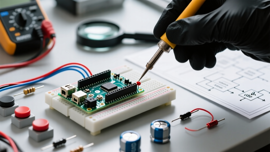

The Physics of Switch Bounce: Why Your Arduino Sees Ghost Presses
When you press a mechanical tactile switch, the metallic contacts do not snap together in a single, clean motion. Instead, kinetic energy causes the contacts to collide, rebound, and vibrate before settling into a stable closed state. To a human finger, this happens instantaneously. To an ATmega328P microcontroller running at 16 MHz, this vibration looks like a rapid-fire sequence of dozens of button presses occurring within a few milliseconds.
This phenomenon, known as switch bounce, is the root cause of erratic behavior in maker projects—from a single button press advancing a menu by three steps to a mechanical relay chattering destructively. Mastering debouncing in Arduino requires understanding that there is no universal 'one-size-fits-all' solution. The right fix depends on your switch metallurgy, wiring distance, and CPU overhead constraints.
Step 1: Diagnosing and Measuring Bounce Time
Before applying a fix, you must quantify the problem. Bounce duration varies wildly based on the switch's internal mechanics. A high-quality Omron B3F series tactile switch typically exhibits 1ms to 2ms of bounce. Conversely, unbranded, mass-produced 6x6mm tactile switches sourced from bulk marketplaces can bounce erratically for 10ms to 20ms, sometimes even exhibiting secondary bounce upon release.
The Oscilloscope vs. The Interrupt Counter
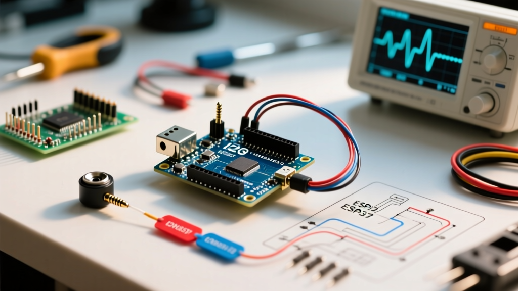
If you have access to a digital storage oscilloscope (DSO), connect the probe to the switch node, set the trigger to 'falling edge', and capture at 10µs/div. You will visibly see the voltage rail oscillating between VCC and GND.
If you lack a DSO, you can diagnose the bounce using the Arduino's hardware interrupts. By attaching an interrupt service routine (ISR) to the switch pin and incrementing a volatile counter on every FALLING edge, a single physical button press will often yield a serial monitor output of 15 to 40 'presses'. This raw data tells you exactly how aggressive your debounce window needs to be.
Hardware Fixes: Filtering the Signal at the Source
Hardware debouncing is mandatory in environments where CPU cycles are precious, or when dealing with external interrupts that cannot afford software latency. The gold standard for hardware debouncing is the RC Low-Pass Filter paired with a Schmitt Trigger.
The RC Filter + Schmitt Trigger Gold Standard
A simple Resistor-Capacitor (RC) network smooths out the high-frequency voltage spikes caused by contact bounce. However, feeding a slow-charging RC curve directly into a standard digital logic gate can cause the gate to oscillate wildly as the voltage crosses the undefined region between logic LOW and HIGH thresholds.
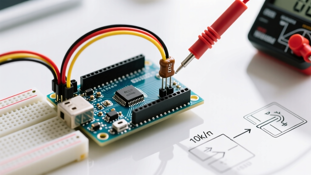
- The RC Network: Use a 10kΩ pull-up resistor and a 100nF (0.1µF) X7R ceramic capacitor wired from the switch node to ground. This creates a time constant (τ = R × C) of 1ms. The capacitor will absorb the bounce energy, but the resulting voltage edge will be a slow, sloping curve.
- The Schmitt Trigger: To square off that slow curve into a crisp digital edge, route the RC signal through a Schmitt trigger inverter, such as the 74HC14 or CD40106. These ICs feature built-in hysteresis—they require the voltage to cross a higher threshold to register a HIGH, and drop below a lower threshold to register a LOW, completely eliminating edge oscillation.
Expert Component Tip: Avoid using Y5V or Z5U dielectric capacitors for your RC debounce filter. Their capacitance drops drastically under DC bias and temperature variations. Always specify X7R or C0G/NP0 ceramic capacitors to ensure your τ time constant remains stable across varying environmental conditions.
Software Fixes: Non-Blocking Debounce Algorithms
For most hobbyist and standard industrial applications, handling debouncing in Arduino via software is more cost-effective and requires fewer PCB components. However, the implementation dictates the reliability of your entire sketch.
Why the delay() Function is a Beginner Trap
The most common tutorial approach involves reading the pin, and if a change is detected, calling delay(50) to 'wait out' the bounce. While this works for a single-button blinking LED, it is catastrophic for complex systems. The delay() function halts the main loop, blinding your Arduino to sensor inputs, serial data, and motor control timings for 50 milliseconds. In a 2026 robotics context, a 50ms blind spot can cause a PID loop to destabilize or a safety limit switch to be missed entirely.
Implementing the State-Machine Approach (Bounce2)
The modern standard for software debouncing is the state-machine approach, best exemplified by the widely adopted Bounce2 Library. Instead of blocking the CPU, Bounce2 tracks the time elapsed since the last pin state change using millis().
When the pin changes state, the library records the timestamp but does not immediately update the logical button state. It waits until the pin has remained stable for the user-defined debounce interval (e.g., 10ms). Only then does it update the internal state flag. This allows your main loop() to run thousands of times per second, continuously polling the .update() method without any blocking delays.
Comparison Matrix: Hardware vs. Software Debouncing
Choosing the right debouncing in Arduino strategy requires balancing bill of materials (BOM) cost, CPU overhead, and response latency. Below is a decision matrix for system architects:
| Method | BOM Cost | CPU Overhead | Latency / Response | Best Use Case |
|---|---|---|---|---|
| RC Filter + 74HC14 | ~$0.45 per switch | Zero (Hardware handled) | ~2-5ms (Analog settling) | External interrupts, sleep-mode wakeups, noisy environments. |
| Software (delay) | $0.00 | 100% Blocked during delay | 50ms+ (Blind spot) | Beginner tutorials only. Never use in production. |
| Software (millis/Bounce2) | $0.00 | Minimal (~2µs per poll) | 10-20ms (Configurable) | Standard UI buttons, menu navigation, matrix keypads. |
| Hardware Timer Interrupt | $0.00 | Low (ISR context switching) | 1-5ms (High precision) | High-speed encoders, precision frequency counting. |
Edge Cases: Long Wires and EMI Environments
A frequent failure mode in DIY home automation and industrial retrofits occurs when a tactile or limit switch is located meters away from the Arduino. Long unshielded wires act as antennas, picking up Electromagnetic Interference (EMI) and Radio Frequency Interference (RFI) from nearby AC mains, VFDs, or switching power supplies.
In these scenarios, software debouncing will fail because the EMI induces voltage spikes that mimic legitimate switch closures, and the noise may persist longer than your software debounce window. The comprehensive guide on switch bounce by All About Circuits highlights that physical signal conditioning is mandatory here.
The Fix: Use an optocoupler (such as the PC817) to provide galvanic isolation between the noisy switch environment and the Arduino's 5V/3.3V logic. Combine this with a hardware RC filter on the high-voltage side of the optocoupler. The official Arduino debounce documentation provides a solid baseline for the software side, but when dealing with 24V industrial limit switches over 5-meter cable runs, hardware isolation combined with a Schmitt trigger is the only reliable path forward.
Summary and Next Steps
Troubleshooting erratic inputs requires moving beyond the naive delay() function. For 90% of maker projects, implementing a non-blocking software library like Bounce2 with a 10ms to 20ms window will completely resolve tactile switch bounce. However, if your project relies on hardware interrupts, operates in high-EMI environments, or demands ultra-low latency, you must design a hardware RC filter paired with a Schmitt trigger inverter. By matching the debounce strategy to the physical realities of your switch metallurgy and wiring topology, you ensure your microcontroller registers every intentional press—and ignores the physics of the bounce.