
The Anatomy of a Dead Digital Pin
There are few things more frustrating in a maker's workflow than uploading a flawless sketch, wiring up your sensors, and realizing that your digital pins Arduino setup is completely unresponsive. You expect a crisp 5V or 3.3V logic HIGH, but your multimeter reads a floating 1.2V, or worse, a dead 0V. Whether you are working with a classic Arduino Uno R3 (ATmega328P) or the newer Arduino Uno R4 Minima (Renesas RA4M1), a non-responsive digital I/O pin usually points to one of three culprits: software misconfiguration, peripheral overcurrent damage, or architectural misunderstandings regarding logic levels.
In this comprehensive troubleshooting guide, we will bypass the generic 'check your wiring' advice and dive deep into the electrical and programmatic realities of microcontroller I/O ports. We will cover exact current thresholds, multimeter diagnostic procedures, and advanced workarounds to salvage a board with fried GPIO headers.
Hardware vs. Software: The Multimeter Diagnostic Flow
Before you rewrite your C++ sketch or blame a counterfeit clone board, you must isolate the domain of the failure. Is the microcontroller failing to execute the digitalWrite() command, or is the physical silicon unable to source current?
Step 1: The Bare-Minimum Blink Isolation
Strip your code down to the absolute minimum. Remove all libraries, interrupt service routines (ISRs), and complex logic. Upload a raw loop that toggles the suspect pin (e.g., Pin 8) with a 1000ms delay. According to the official Arduino Language Reference for pinMode, failing to explicitly declare pinMode(8, OUTPUT) defaults the pin to a high-impedance INPUT state. In this state, the pin will not source meaningful current, and a high-impedance multimeter might read ghost voltages induced by nearby electromagnetic interference.
Step 2: Probing the Physical Header
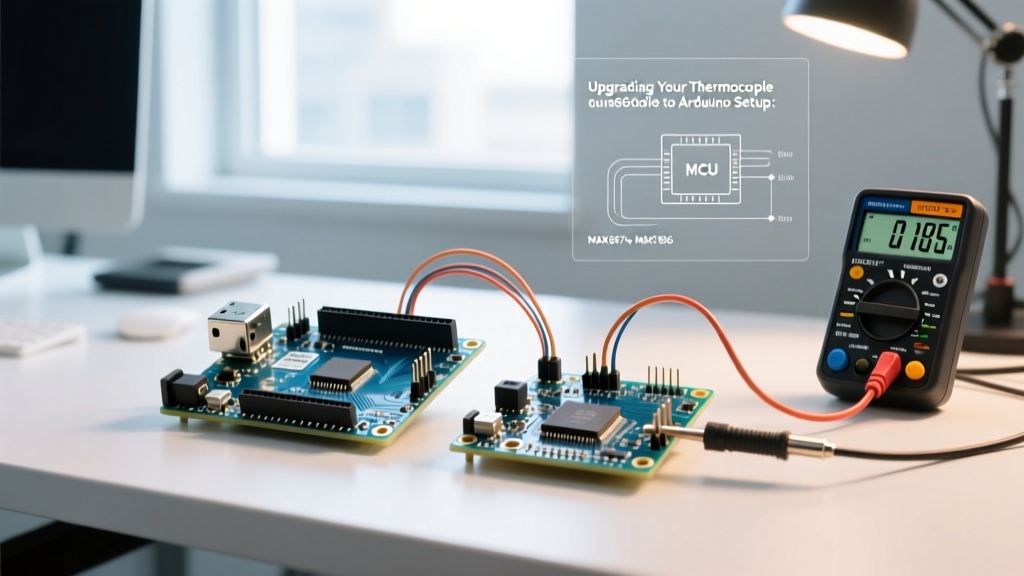
Set your digital multimeter (a True-RMS meter like the Fluke 117 or Brymen BM235 is highly recommended for accurate DC readings) to DC Voltage. Place the black probe firmly on the GND header and the red probe on the suspect digital pin. If the code is executing a HIGH state, an ATmega328P-based board should read between 4.8V and 5.1V. If you read 0V, proceed to the hardware failure matrix below.
Common Failure Modes and Solutions
| Symptom | Probable Cause | Technical Fix / Workaround |
|---|---|---|
| Pin reads 0V constantly | Short circuit to GND on breadboard or shield; blown internal P-channel MOSFET. | Remove all external wiring. Retest. If still 0V, the pin is permanently dead. Use Analog pins as digital fallback. |
| Pin reads ~1.5V to 2.5V (floating) | Pin configured as INPUT without pull-up; reading environmental noise. | Add pinMode(pin, INPUT_PULLUP) in setup, or wire a physical 10kΩ pull-up resistor to VCC. |
| Pin outputs 5V but drops to 2V under load | Exceeding the 20mA recommended source limit; triggering internal thermal protection. | Use a logic-level MOSFET (e.g., IRLZ44N) or a BJT (2N2222) to switch high-current loads. Never drive motors directly. |
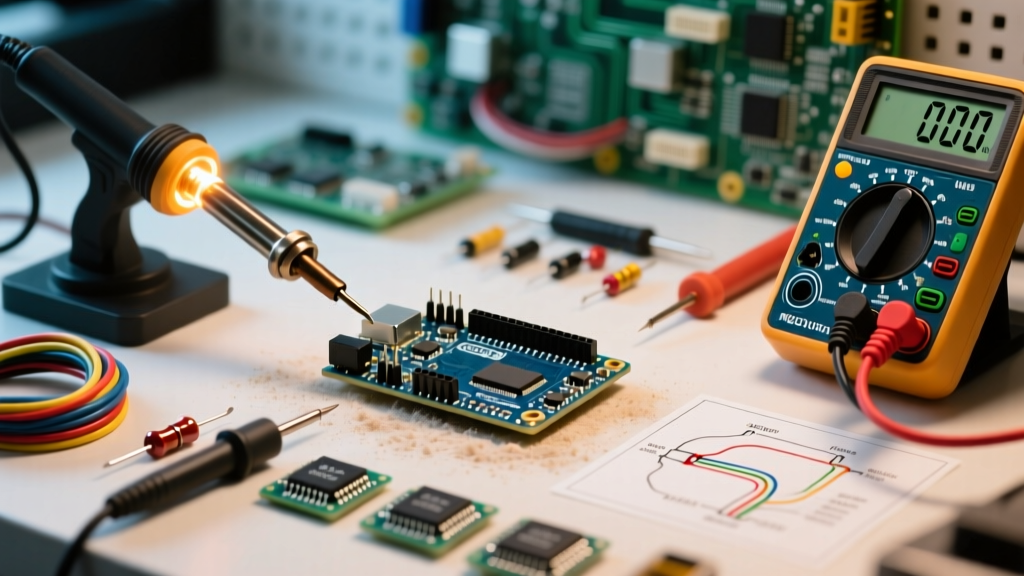
| Pin works intermittently when touched | Cold solder joint on the female header; micro-fracture in the PCB trace. | Reflow the header pins with a 350°C iron and 63/37 rosin-core solder. Check continuity from the MCU leg to the header. |
The Inductive Kickback Scenario: Why Pins Die Suddenly
One of the most common reasons for sudden, irreversible digital pin failure on an Arduino is the omission of a flyback diode when driving inductive loads. If you have ever wired a 5V relay module directly to a digital pin without an optocoupler or a consultation of the ATmega328P datasheet's absolute maximum ratings, you have likely experienced this.
When a relay coil is energized, it builds a magnetic field. When the digital pin goes LOW and cuts the current, the collapsing magnetic field induces a massive reverse voltage spike (Back-EMF) that can easily exceed 50V. This spike travels backward into the microcontroller's I/O pin, instantly punching through the internal ESD protection diodes and melting the silicon trace. The pin is now permanently shorted to ground or VCC.
Expert Fix: Always place a 1N4007 or 1N4148 switching diode in reverse bias across the coil of any relay, solenoid, or DC motor. The cathode (stripe) must face the positive voltage source. This provides a safe recirculation path for the inductive spike, protecting your Arduino's digital headers.
Architecture Shift: Uno R3 (5V) vs. Uno R4 (3.3V Logic)
As we navigate the maker landscape in 2026, the transition from 5V to 3.3V logic architectures has introduced a new layer of troubleshooting for digital pins Arduino users. The classic Arduino Uno R3 operates at a native 5V logic level. However, the Arduino Uno R4 Minima, powered by the 32-bit Renesas RA4M1 Cortex-M4, operates at 3.3V logic.
If you are migrating an older project to an Uno R4 and your digital pins are not triggering external 5V modules (like the HC-SR04 ultrasonic sensor or standard 5V relay boards), the issue is not a broken pin—it is a logic threshold mismatch. The 3.3V HIGH output from the R4 may not cross the 3.5V minimum threshold required by older 5V TTL components. Furthermore, while select pins on the R4 are 5V-tolerant for inputs, feeding 5V back into a non-tolerant R4 digital pin configured as an OUTPUT will fry the Renesas GPIO port matrix. Always use a bidirectional logic level converter (like the Texas Instruments TXS0108E) when bridging 3.3V Arduinos with legacy 5V peripherals.
Advanced Recovery: Port Register Manipulation
Sometimes, the standard digitalWrite() function fails to behave as expected due to timer conflicts. If you are using libraries that rely on hardware timers (such as Servo.h, Tone, or certain PWM motor controllers), they may hijack the timer associated with specific digital pins (like Pins 9 and 10 on the Uno R3, which share Timer1). If your pin is stuck in a PWM state and ignoring your digital HIGH/LOW commands, you can bypass the Arduino abstraction layer and write directly to the AVR port registers.
For example, digital pins 8 through 13 on the ATmega328P map to PORTB. You can force Pin 8 (PB0) HIGH instantly, bypassing any timer interrupts, using direct bitwise operations:
// Set PB0 (Pin 8) as OUTPUT
DDRB |= (1 << DDB0);
// Force PB0 HIGH
PORTB |= (1 << PORTB0);
// Force PB0 LOW
PORTB &= ~(1 << PORTB0);
This method is not only immune to software timer conflicts but also executes in a single clock cycle (62.5 nanoseconds on a 16MHz board), compared to the several microseconds required by the standard digitalWrite() function.
The Fallback Plan: Repurposing Analog Pins as Digital I/O
If your diagnostic testing confirms that a specific digital pin (e.g., D3) has suffered irreversible silicon damage from an overcurrent event, your board is not necessarily e-waste. The ATmega328P features six analog input pins (A0 through A5) that can be seamlessly reconfigured as standard digital I/O pins.
In the Arduino IDE, you can reference these pins using their analog designations or their digital equivalents (14 through 19). For instance, if D3 is dead, you can wire your component to A0 and update your code:
pinMode(A0, OUTPUT);
digitalWrite(A0, HIGH);
These analog-digital hybrid pins support the exact same 20mA source/sink limits and internal pull-up resistors as the standard D0-D13 headers, providing a vital lifeline for field repairs and rapid prototyping when you cannot wait for a replacement microcontroller to ship.