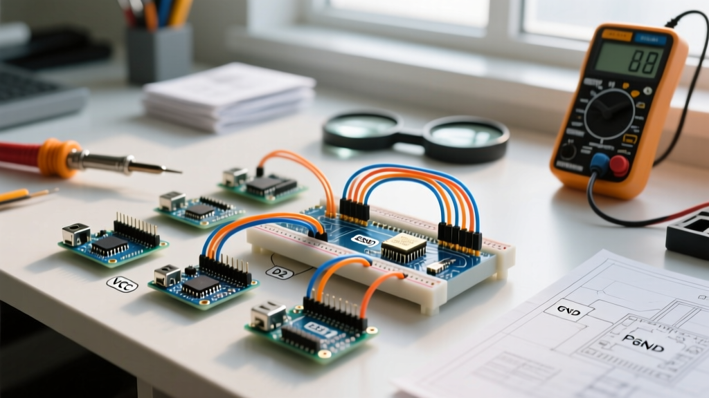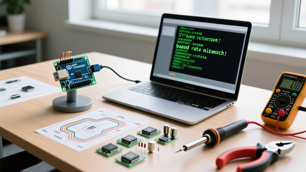

The Anatomy of a Baud Rate Arduino Mismatch
Serial communication is the foundational diagnostic tool in embedded systems, yet it remains one of the most frequent sources of frustration for makers and engineers. When a baud rate Arduino mismatch occurs, the symptoms range from minor annoyances like garbled text to complete development halts caused by bootloader upload failures. Unlike SPI or I2C, Universal Asynchronous Receiver-Transmitter (UART) communication does not share a dedicated clock line. Instead, the transmitter and receiver must independently agree on the exact timing of bit transitions based on a pre-configured baud rate (bits per second).
If the transmitting device (e.g., an ATmega328P microcontroller) and the receiving device (e.g., a CP2102 USB-to-UART bridge or your PC's Serial Monitor) operate on slightly different clock assumptions, the receiver's sampling point will drift. By the 7th or 8th bit of a byte, the receiver may sample the falling edge of a pulse instead of the stable center, interpreting a logical '1' as a '0'. According to SparkFun's Serial Communication Guide, an error margin exceeding 2% to 3% on either side of the link is typically enough to corrupt data frames, resulting in framing errors and dropped packets.
Symptom 1: Garbage Characters in the Serial Monitor
The most ubiquitous serial error manifests as a stream of nonsensical characters—often ÿ, ?, or random Wingdings—in the Arduino IDE 2.x Serial Monitor. This is rarely a hardware failure; it is almost always a software configuration mismatch.
The Diagnosis Protocol
- Verify the Sketch Definition: Check your
setup()function for theSerial.begin()declaration. As noted in the official Arduino Serial.begin() reference, standard rates include 9600, 38400, 57600, and 115200. - Match the IDE Dropdown: Look at the bottom right corner of the Arduino IDE Serial Monitor. Ensure the dropdown exactly matches the integer passed to
Serial.begin(). - Check for Dual-Use Conflicts: If you are using an ESP32 or a board with native USB (like the Leonardo or Micro), ensure you aren't accidentally routing hardware UART pins (GPIO 1/3 on ESP32) to a secondary serial bridge while monitoring the native USB CDC port.
Symptom 2: Upload Failures and Avrdude Errors
A more critical failure occurs when the Arduino IDE fails to upload a sketch, throwing the dreaded avrdude: stk500_recv(): programmer is not responding error. This is deeply tied to the Optiboot bootloader's baud rate expectations.
Expert Insight: The Optiboot bootloader on standard 16MHz Arduino Uno and Nano clones listens for the initial handshake at exactly 115200 baud. If your board is configured in the IDE as an 8MHz 'Pro Mini' but physically possesses a 16MHz crystal, the bootloader will transmit its response at 230400 baud relative to the IDE's 115200 expectation, instantly breaking the handshake.
Fixing Bootloader Baud Rate Drift
- Board Definition Mismatch: Ensure the IDE 'Board' and 'Processor' selections match the physical crystal on the PCB. A 16MHz crystal requires the 'ATmega328P (5V, 16MHz)' selection.
- Corrupted Bootloader: If the correct board is selected but uploads still fail, the bootloader's internal fuse bits may be corrupted. Use an ISP programmer (like a USBasp or Arduino as ISP) and select Tools > Burn Bootloader to re-flash the Optiboot hex file and reset the UART timing fuses.
Oscillator Frequency vs. Baud Rate Error Margins
Not all baud rates are created equal. The ATmega328P generates its UART timing by dividing the system clock. Because 16MHz and 8MHz cannot be divided perfectly into every standard baud rate, hardware-level rounding errors occur. The Microchip ATmega328P Datasheet explicitly outlines these error margins. If the error exceeds the tolerance of your USB-UART bridge, data will drop.
| Target Baud Rate | 16MHz Quartz Crystal (Error %) | 8MHz Quartz Crystal (Error %) | 8MHz Internal RC Oscillator (Error %) |
|---|---|---|---|
| 9600 | 0.2% (Safe) | 0.2% (Safe) | ~3.5% (Marginal) |
| 38400 | 0.8% (Safe) | 0.8% (Safe) | ~7.0% (Fail) |
| 57600 | 2.1% (Marginal) | 2.1% (Marginal) | ~8.5% (Fail) |
| 115200 | 2.1% (Marginal) | 2.1% (Marginal) | ~12.0% (Fail) |
Takeaway: If you are designing a bare-bones ATmega328P circuit using the internal 8MHz RC oscillator to save space and cost, you must limit your serial communication to 9600 baud. Attempting 115200 baud on an internal RC oscillator will result in catastrophic framing errors due to the ~12% timing drift, exacerbated by temperature-induced RC frequency shifting.
Symptom 3: Intermittent Drops with Third-Party USB-UART Chips
In 2026, the maker market is flooded with clone boards utilizing various USB-to-Serial ICs. The specific IC on your board drastically affects high-speed baud rate stability.
IC Comparison Matrix
- CH340G / CH340C: Found on 90% of budget Nano/Uno clones. It uses a fractional clock divider that introduces slight phase jitter at non-standard baud rates. It handles 115200 baud fine, but struggles with continuous high-throughput streams at 500000+ baud without hardware flow control (RTS/CTS).
- CP2102N: Silicon Labs' modern bridge. Features a highly precise internal PLL and supports baud rates up to 3Mbaud. Excellent for high-speed data logging where the CH340 would drop bytes.
- FT232RL (and FT232RQ clones): The gold standard for industrial applications. Features a 256-byte receive FIFO buffer that prevents buffer overruns during OS-level USB polling latency spikes. If you are diagnosing missing bytes in a high-speed serial stream, upgrading to an FT232-based adapter is the definitive hardware fix.
SoftwareSerial vs. Hardware UART Limits
A frequent diagnostic blind spot occurs when developers use the SoftwareSerial library to add secondary serial ports on an AVR-based Arduino. Unlike hardware UART, which uses dedicated silicon shift registers, SoftwareSerial relies on CPU pin-change interrupts to time bit transitions.
At 9600 baud, a bit lasts for ~104.16µs, giving the 16MHz CPU roughly 1,666 clock cycles to handle the interrupt and sample the pin. However, at 115200 baud, a bit lasts only ~8.68µs (about 138 clock cycles). Any background interrupt (like the Timer0 millis() overflow) occurring during a SoftwareSerial receive event will cause the CPU to miss the bit boundary. Never use SoftwareSerial above 57600 baud on 8-bit AVR microcontrollers if data integrity is required. For higher speeds, migrate to a microcontroller with multiple hardware UARTs, such as the ATmega2560 (Mega 2560) or the ESP32 (which features three hardware UARTs).
Advanced Diagnosis: Logic Analyzer Verification
When software configurations and oscillator assumptions have been ruled out, you must verify the physical layer. Connect a low-cost logic analyzer (such as a Saleae Logic clone or a Sigrok-compatible DSLogic) to the TX pin of the Arduino and the RX pin of the receiver.
Measurement Steps
- Set the logic analyzer sample rate to at least 10 MHz (10x the target baud rate frequency) to ensure precise edge detection.
- Trigger on the falling edge of the UART Start Bit.
- Measure the duration of the first data bit. For 9600 baud, the cursor-to-cursor measurement must read 104.1µs ± 2µs.
- If the measured bit width deviates significantly (e.g., reads 98µs), your microcontroller's crystal oscillator is either the wrong frequency, severely out of tolerance, or suffering from capacitive load mismatch on the PCB.
Summary Resolution Checklist
To systematically eliminate baud rate Arduino errors, follow this exact sequence:
- Confirm
Serial.begin(X)matches the IDE Serial Monitor dropdown. - Verify the IDE 'Board' and 'Processor' clock speed matches the physical crystal on the PCB.
- Reduce baud rate to 9600 to test if the issue is an internal RC oscillator drift or SoftwareSerial interrupt collision.
- Swap the USB cable and test a different USB-UART bridge IC (preferably FT232RL) to rule out PC-side driver/buffer latency.
- Probe the TX line with a logic analyzer to mathematically verify the physical bit-width timing.
By understanding the mathematical relationship between system clocks, UART dividers, and physical oscillator tolerances, you can transition from guessing to definitively engineering reliable serial communication links.