
The 'Charge-Only' Trap: Why Your Arduino Won't Connect
Every maker has experienced the frustration of plugging a fresh microcontroller into their PC, only to be met with the dreaded 'Port not found' or 'Device Descriptor Request Failed' error in the IDE. Before you blame a corrupted bootloader, a faulty ATmega chip, or a missing driver, look closely at the wire in your hand. The vast majority of connectivity issues in the maker space stem from using a charge-only cable. As of 2026, with the market flooded by cheap USB cables bundled with consumer electronics, understanding cable Arduino compatibility is no longer optional—it is a fundamental troubleshooting skill.
This comprehensive compatibility guide breaks down the physical connectors, internal wiring topologies, and signal integrity requirements needed to successfully program and power your development boards. Whether you are reviving a classic Arduino Uno R3 or deploying a modern USB Type-C equipped Arduino Uno R4, choosing the right cable dictates the success of your project.
The Anatomy of a Data Cable vs. a Charge Cable
To understand compatibility, we must first look inside the jacket of a standard USB 2.0 cable. A fully compliant USB 2.0 data cable contains four primary conductors, each serving a distinct purpose:
- VBUS (Red): Carries +5V DC power from the host to the device.
- GND (Black): The ground return path for both power and data signals.
- D- (White): The negative differential data line.
- D+ (Green): The positive differential data line.
Charge-only cables, commonly bundled with cheap desk fans, LED strips, or low-end earbuds, intentionally omit the D- and D+ wires to save on manufacturing costs. When you plug a charge-only cable into an Arduino Nano or Uno, the board will power on (the 'ON' LED will illuminate), but the IDE will never detect the serial port. The physical connection for data simply does not exist.
Wire Gauge and Voltage Drop
Even among genuine data cables, wire gauge matters significantly. According to the USB Implementers Forum (USB-IF) specifications, standard data lines should be 28 AWG (American Wire Gauge), while power lines should be 24 AWG or thicker. If you use a 2-meter cable with ultra-thin 30 AWG power lines to program an Arduino Mega 2560 equipped with a motor shield, the voltage drop across the cable can exceed 0.5V. This drops the voltage at the board's USB connector below the 4.75V threshold, causing the onboard 5V regulator to brownout precisely when the board draws peak current during a sketch upload.
Board-to-Connector Compatibility Matrix
The Arduino ecosystem has evolved significantly over the last decade, transitioning through several USB standards. Use the matrix below to identify the exact cable Arduino configuration your specific board requires.
| Board Model | Connector Type | Cable Required | USB Spec & Bridge Chip |
|---|---|---|---|
| Arduino Uno R3 | USB Type-B | USB-A to USB-B (Standard Printer Cable) | USB 2.0 Full-Speed (ATmega16U2) |
| Arduino Mega 2560 | USB Type-B | USB-A to USB-B | USB 2.0 Full-Speed (ATmega16U2) |
| Arduino Nano (Classic) | Mini-USB (5-pin) | USB-A to Mini-B | USB 2.0 (FTDI FT232RL) |
| Arduino Nano Every / 33 IoT | Micro-USB | USB-A to Micro-B | USB 2.0 (Integrated / Bridge) |
| Arduino Uno R4 Minima / WiFi | USB Type-C | USB-A to Type-C or Type-C to Type-C | USB 2.0 (Native RA4M1 / ESP32-S3) |
| Arduino GIGA R1 WiFi | USB Type-C | USB Type-C (Data Rated) | USB 2.0 High-Speed (STM32H7) |
The Type-C Transition: Uno R4 and Modern Clones
With the release of the Arduino Uno R4 series and the widespread adoption of ESP32-S3 development boards, USB Type-C has become the standard for modern makers. However, Type-C introduces a new layer of compatibility complexity: the Configuration Channel (CC).
Unlike Micro-USB, which blindly outputs 5V when plugged into a host port, USB Type-C requires the device to signal its presence. The Arduino board must have 5.1kΩ pull-down resistors on the CC1 and CC2 pins. When a compliant host port detects these resistors, it enables the 5V VBUS output. If you are using cheap third-party clone boards that omitted these resistors to save fractions of a cent, the cable will not trigger the host port to deliver power, leaving the board completely dead.
Pro-Tip for Type-C Users: Not all Type-C cables are created equal. Some 'USB-C to USB-C' cables designed exclusively for high-wattage laptop charging (100W+) lack the internal USB 2.0 data wires (D+/D-), relying entirely on high-speed SuperSpeed pairs that older microcontroller USB peripherals cannot negotiate. Always verify that your Type-C cable explicitly supports 'Data Transfer up to 480Mbps' on the packaging.
Signal Integrity: CH340 Clones vs. Genuine 16U2
When sourcing cables for clone boards, you must account for the USB-to-Serial bridge chip. Genuine Arduino boards utilize the Microchip ATmega16U2, a robust microcontroller acting as a USB bridge. Most budget clones utilize the WCH CH340G or Silicon Labs CP2102 chips.
The CH340G is notoriously sensitive to cable capacitance and electromagnetic interference (EMI). USB 2.0 Full-Speed operates at 12 Mbps, requiring relatively sharp square-wave transitions on the D+ and D- lines. Poorly shielded, high-capacitance cables (exceeding 50pF per meter) will 'round off' the edges of these signals. While a genuine 16U2 might still successfully decode the degraded signal, the CH340G will frequently fail enumeration, resulting in the Windows Device Manager error: 'Unknown USB Device (Device Descriptor Request Failed).'
If you are working with CH340-based clones, keep your cable length under 1 meter and prioritize cables with braided shielding and ferrite beads.
Troubleshooting Matrix: Is it the Cable or the Board?
Use this diagnostic matrix to isolate whether your connectivity failure is caused by the cable Arduino setup or a deeper hardware fault. For more advanced IDE troubleshooting, refer to the Arduino Official Documentation.
- Symptom: Board powers on (LED lit), but no COM port appears in IDE.
Verdict: 95% chance of a charge-only cable. 5% chance of missing CH340/FTDI drivers. - Symptom: COM port appears, but upload fails at 99% with 'avrdude: stk500_recv() programmer is not responding'.
Verdict: Cable has data lines, but suffers from severe EMI interference or voltage drop during the high-current flash memory write cycle. Switch to a shorter, shielded cable. - Symptom: 'Unknown USB Device' pops up immediately upon plugging in.
Verdict: Data lines (D+/D-) are physically broken inside the cable jacket, or the cable's capacitance is too high for the clone board's bridge chip to handle. - Symptom: USB Type-C cable works on a phone, but Arduino Uno R4 remains dead.
Verdict: The cable lacks internal USB 2.0 legacy data wires, or the clone board is missing the 5.1kΩ CC pull-down resistors.
How to Test Your Cable with a Multimeter
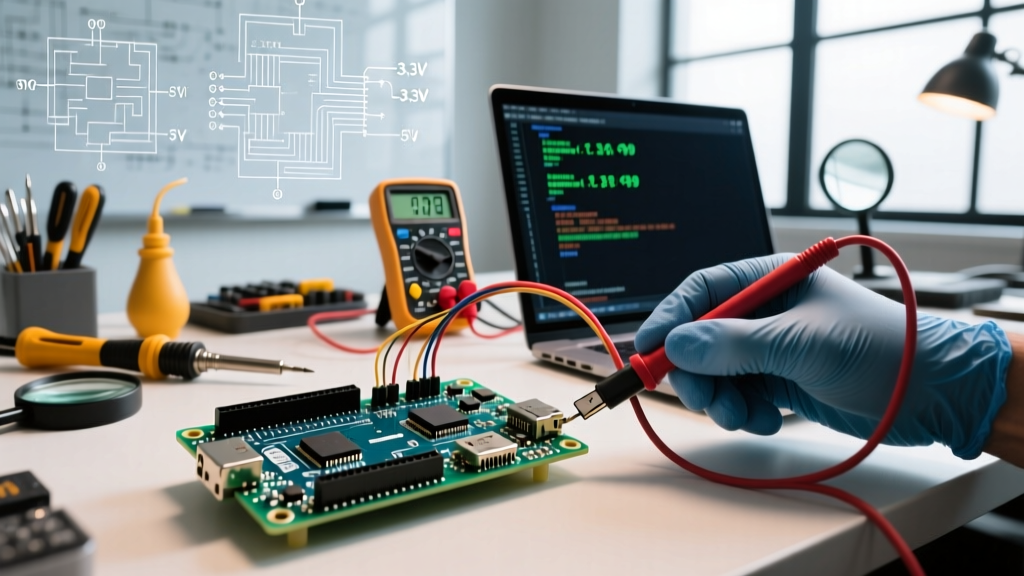
If you have a drawer full of unmarked Micro-USB or Mini-USB cables, you can verify their data capabilities in under 60 seconds using a standard digital multimeter.
- Set your multimeter to the Continuity setting (the mode that beeps when the probes touch).
- Plug the USB-A end into a dummy block or hold it securely.
- Identify the pins on the USB-A connector: Pin 1 is VBUS (left), Pin 4 is GND (right). Pins 2 and 3 are the inner D- and D+ data lines.
- Touch one probe to Pin 2 (D-) on the USB-A end, and the other probe to the corresponding D- pin on the Micro/Mini connector. You should hear a continuous beep.
- Repeat for Pin 3 (D+). If the multimeter does not beep on the inner pins, the cable is strictly for charging and belongs in the recycling bin.
Best Practices for the Maker Desk
To maintain a frictionless workflow, adopt a strict cable management protocol. Use velcro ties or colored heat-shrink tubing to physically mark your verified data cables. Never mix them in a drawer with charge-only cables salvaged from consumer gadgets. Investing $8 to $12 in three high-quality, braided, 28 AWG data cables (one Type-B, one Micro-B, and one Type-C) will save you hours of debugging time and protect your hardware from the erratic voltage drops inherent in cheap, mass-produced wires.