
The Ultimate 10k Potentiometer Arduino Quick Reference
The 10k ohm potentiometer is the undisputed workhorse of analog input control in microcontroller projects. Whether you are building a MIDI controller, tuning a PID feedback loop, or simply dimming an LED, the interaction between a 10k potentiometer Arduino setup and the onboard Analog-to-Digital Converter (ADC) requires precise electrical matching. In 2026, despite the rise of capacitive touch and magnetic Hall-effect sensors, physical resistive potentiometers remain essential for tactile, high-reliability analog control.
This quick-reference FAQ and troubleshooting guide bypasses the fluff, delivering exact impedance calculations, noise-filtering schematics, and production-grade code snippets for your next build.
Quick-Reference Wiring Matrix
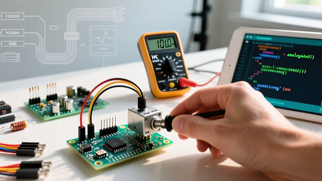
A potentiometer is fundamentally a three-terminal voltage divider. Correct mapping to the Arduino Uno (ATmega328P) or Nano is critical to avoid floating pins and erratic ADC readings.
| Potentiometer Pin | Arduino Connection | Wire Color (Standard) | Function & Notes |
|---|---|---|---|
| Pin 1 (CCW) | GND | Black | Connects to the internal carbon track ground. Reversing Pin 1 and Pin 3 inverts the analog scale (1023 to 0 instead of 0 to 1023). |
| Pin 2 (Wiper) | Analog Pin (e.g., A0) | Yellow/Signal | The variable output. Must include a 100nF decoupling capacitor to GND for noise suppression. |
| Pin 3 (CW) | 5V (or 3.3V) | Red | Reference voltage. Ensure this matches your board's logic level to prevent ADC overvoltage damage. |
Frequently Asked Questions (FAQ)
1. Why use a 10k potentiometer instead of 1k or 100k for Arduino?
This is the most common question among beginners, and the answer lies in the ATmega328P datasheet. The Arduino's ADC uses a Successive Approximation Register (SAR) architecture with an internal sample-and-hold (S&H) capacitor of approximately 14pF. According to official Arduino analog reference documentation, the recommended maximum source impedance for reliable 10-bit resolution is 10kΩ.
When you wire a potentiometer as a voltage divider, the Thevenin equivalent resistance is highest when the wiper is at the exact 50% midpoint. The formula for this maximum output impedance is R_total / 4.
- 10kΩ Potentiometer: Max impedance is 2.5kΩ. This easily charges the 14pF S&H capacitor within the 1.5 ADC clock cycles allocated for sampling, ensuring accurate, linear readings across the entire 0-1023 range.
- 100kΩ Potentiometer: Max impedance is 25kΩ. The internal capacitor cannot fully charge in time, resulting in non-linear errors, 'sticking' values in the mid-range, and heavy susceptibility to electromagnetic interference (EMI).
- 1kΩ Potentiometer: Max impedance is a safe 250Ω, but it draws 5mA of continuous current from the 5V rail (I = V/R), wasting power and generating unnecessary heat in battery-operated IoT nodes.
Verdict: The 10k potentiometer Arduino combination is the mathematical sweet spot between ADC charging speed and power consumption.
2. How do I stop my analog readings from jumping or fluctuating?
Analog pins act as high-impedance antennas, picking up 50/60Hz mains hum and high-frequency switching noise from nearby DC-DC converters or PWM outputs. To achieve rock-solid readings, you must implement a two-tier filtering approach:
Hardware Filter (Low-Pass RC):
Solder a 100nF (0.1µF) X7R ceramic capacitor directly between the wiper pin (Pin 2) and GND (Pin 1). This creates a first-order low-pass filter. Using the maximum Thevenin resistance of 2.5kΩ, the cutoff frequency is calculated as:
f_c = 1 / (2π × R × C) = 1 / (2π × 2500 × 0.0000001) ≈ 636 Hz
This effectively shunts high-frequency EMI to ground while remaining entirely unresponsive to human turning speeds (which rarely exceed 5Hz).
Software Filter (Exponential Moving Average):
For residual low-frequency jitter, avoid the standard `analogRead()` delay traps. Instead, use an Exponential Moving Average (EMA) filter in your C++ sketch. See the code section below for the exact implementation.
3. Can I wire multiple 10k potentiometers to a single Arduino Uno?
Yes. The ATmega328P has six dedicated ADC channels (A0 to A5). Because the 10k pots draw a negligible 0.5mA each, wiring six of them directly to the 5V rail draws only 3mA total—well within the Arduino's 500mA USB limit and the internal trace limits. If your project requires more than six knobs (e.g., a 16-channel MIDI mixer), do not use standard GPIO pins. Instead, multiplex the analog signals using a CD4051B 8-channel analog multiplexer or a CD4067B 16-channel multiplexer, which interfaces with the Arduino via just three digital control pins and one analog input pin.
Production-Grade Arduino Code (EMA Noise Filter)
The built-in SparkFun voltage divider tutorials often show basic `analogRead()` loops. For production environments where a jumping value could trigger a false threshold in a motor controller, use this EMA algorithm. It requires zero external libraries and executes in microseconds.
// 10k Potentiometer Arduino EMA Filter Code
const int POT_PIN = A0;
const float ALPHA = 0.05; // Smoothing factor (0.01 to 0.99). Lower = smoother but slower.

float filteredValue = 0.0;
bool isFirstRead = true;

void setup() {
  Serial.begin(115200);
  analogReadResolution(10); // Explicitly set 10-bit for standard AVR boards
}

void loop() {
  int rawValue = analogRead(POT_PIN);

  if (isFirstRead) {
    filteredValue = rawValue; // Seed the filter on boot
    isFirstRead = false;
  } else {
    // EMA Formula: Output = (Alpha * New_Input) + ((1 - Alpha) * Previous_Output)
    filteredValue = (ALPHA * rawValue) + ((1.0 - ALPHA) * filteredValue);
  }

  // Map the stable float back to an integer for standard Arduino logic
  int stableOutput = (int)filteredValue;

  Serial.print("Raw: ");
  Serial.print(rawValue);
  Serial.print(" | Stable: ");
  Serial.println(stableOutput);

  delay(10); // 100Hz sampling rate
}
Hardware Buying Guide: Tapers and Build Quality (2026 Market)
When sourcing components for a 10k potentiometer Arduino project, the resistance value is only half the battle. The taper (how resistance changes relative to shaft rotation) and the element material dictate the user experience and lifespan.
| Specification | Linear (B10K) | Logarithmic / Audio (A10K) | Recommendation for MCU |
|---|---|---|---|
| Resistance Curve | Strictly proportional (50% turn = 5kΩ). | Exponential curve (mimics human hearing). | ALWAYS use B10K (Linear). |
| Arduino Mapping | Direct 1:1 mapping to servos, LEDs, or motor speed. | Requires complex inverse-log math in C++ to linearize. | Linear saves CPU cycles and prevents UI lag. |
| Common Models | Bourns 3386P, Alpha RD901F | Alps RK09K, Bourns 3386A | Avoid 'A' taper pots for position sensing. |
Element Material Warning: Cheap, unbranded carbon-track potentiometers (often sold in bulk kits for $0.10 each) suffer from 'wiper scratch'—a phenomenon where the physical wiper wears away the carbon element after 5,000 to 10,000 rotations, causing dead spots and infinite resistance spikes. For professional 2026 builds, specify cermet (ceramic-metal) or conductive plastic elements. The Bourns potentiometer lineup offers cermet trimpots (like the 3296W series) rated for 250 cycles with virtually zero contact resistance variation, ideal for internal calibration dials.
Troubleshooting Matrix: Common 10k Potentiometer Failures
When your circuit fails to behave, consult this diagnostic matrix before rewriting your code.
| Symptom | Root Cause | Engineering Fix |
|---|---|---|
| Readings max out at 1023 but never drop to 0. | Pin 1 (GND) is floating or disconnected. | Check continuity from Pot Pin 1 to Arduino GND with a multimeter. Ensure breadboard rails are not split. |
| Values jump erratically between 0 and 1023. | Wiper (Pin 2) is disconnected; pin is floating and acting as an antenna. | Solder or firmly seat the wiper wire. Add a 10kΩ pull-down resistor to GND as a fail-safe. |
| Readings stop at ~850 and won't reach 1023. | Voltage drop across breadboard traces or using a 3.3V pot on a 5V reference. | Measure voltage at Pot Pin 3. If it reads 4.2V instead of 5.0V, move power directly to the Arduino 5V header. |
| Mid-range values are non-linear or 'sticky'. | Source impedance too high (using 50k+ pot) or ADC S&H cap failing to charge. | Replace with a proper 10kΩ B-taper potentiometer. Add a 100nF capacitor at the wiper. |
| Physical rotation feels 'gritty' and values skip. | Carbon track degradation or dust ingress inside the housing. | Inject DeoxIT D5 contact cleaner into the slot, rotate 50 times. If unresolved, replace with a sealed conductive plastic unit. |
Final Pro-Tip for PCB Design
If you are transitioning your 10k potentiometer Arduino prototype to a custom PCB, never route the analog wiper trace parallel to digital clock lines or PWM motor traces. Keep the wiper trace as short as physically possible, route it on an isolated layer if using a 4-layer board, and surround it with a grounded copper pour to create a Faraday cage effect. This eliminates the need for heavy software filtering, freeing up CPU cycles for your core application logic.