
The Reality of IMU Arduino Integrations in 2026
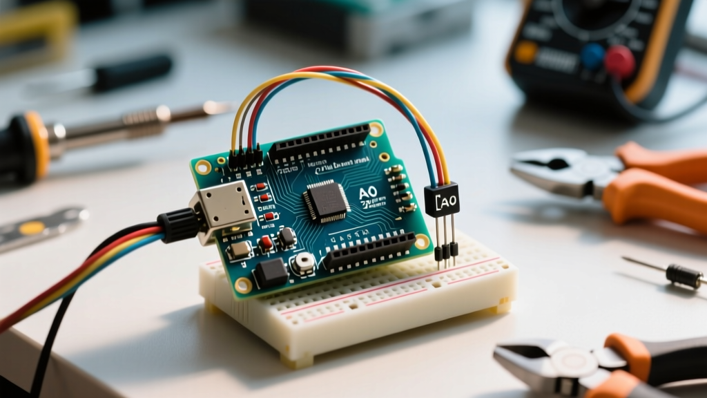
Integrating an Inertial Measurement Unit (IMU) with an Arduino microcontroller is a rite of passage for robotics and drone makers. However, the transition from a breadboard prototype to a reliable embedded system is rarely smooth. Whether you are working with a $2.50 generic MPU6050 clone, a $34.95 Adafruit BNO055 breakout, or the newer CEVA BNO086 modules dominating the 2026 maker market, hardware realities often disrupt your code. I2C bus hangs, unexplainable sensor drift, and logic-level frying are the most frequent culprits.
This comprehensive troubleshooting guide bypasses generic advice and dives deep into register-level debugging, electrical signal integrity, and sensor fusion mathematics to get your IMU Arduino project functioning flawlessly.
The I2C Bus Bottleneck: Why Your Arduino Cannot Find the IMU
The most common failure mode in any IMU Arduino setup is the microcontroller failing to detect the sensor on the I2C bus. When you run an I2C scanner sketch and get no results, or your code hangs indefinitely on Wire.requestFrom(), the issue is almost always electrical or address-related.
Pull-Up Resistor Deficiencies and Bus Capacitance
The I2C protocol requires pull-up resistors on both the SDA (data) and SCL (clock) lines. Many cheap, generic IMU breakout boards claim to have 'onboard pull-ups,' but these are often 10kΩ resistors. While 10kΩ might work for a single sensor on a 5V bus with ultra-short traces, it is entirely inadequate for complex setups.
- The 400pF Capacitance Limit: The I2C specification limits total bus capacitance to 400pF. Standard jumper wires add roughly 15pF to 20pF per 10cm. If you are using long wires or multiple sensors, the RC time constant created by weak 10kΩ pull-ups and high capacitance will round off the square wave signals, causing the Arduino to miss clock edges.
- The Fix: Solder external 4.7kΩ pull-up resistors from both SDA and SCL to the 3.3V logic rail (not 5V, to protect the sensor). If your wire run exceeds 30cm, you must lower the I2C clock speed in your Arduino setup function by adding
Wire.setClock(100000);to drop from Fast Mode (400kHz) to Standard Mode (100kHz).
Address Conflicts and Floating Pins
IMUs typically have a hardware pin to select between two I2C addresses. On the InvenSense MPU6050, this is the AD0 pin. If AD0 is tied to GND, the address is 0x68; if tied high, it is 0x69. On cheap breakout boards, this pin is often left floating. A floating AD0 pin acts as an antenna, picking up electromagnetic interference and causing the sensor's internal address register to flip randomly during operation. Always tie the AD0 pin directly to GND if you are only using one sensor.
Wiring Faults and Voltage Mismatches: The Silent Killers
Frying an IMU sensor is remarkably easy if you ignore logic level thresholds. While the classic Arduino Uno operates at 5V logic, modern high-performance IMUs are strictly 3.3V or even 1.8V devices. Sending a 5V HIGH signal from the Arduino's SDA line directly into a 3.3V IMU will permanently destroy the sensor's I2C transceiver.
IMU Voltage and Logic Level Compatibility Matrix
| IMU Module / Breakout | Vin / Power Input | I2C Logic Level | Direct 5V Arduino Safe? | Typical 2026 Price |
|---|---|---|---|---|
| Generic MPU6050 (Clone) | 3.3V - 5V (via onboard LDO) | 3.3V (Technically 5V tolerant but risky) | Risky (Use level shifter for longevity) | $2.50 - $4.00 |
| Adafruit BNO055 Breakout | 3.3V - 5V | 3.3V or 5V (Onboard MOSFET shifters) | Yes, completely safe | $34.95 |
| SparkFun ICM-20948 | 3.3V Only | Strict 3.3V | No (Requires Bi-directional Level Shifter) | $19.95 |
| CEVA BNO085 / BNO086 | 3.3V Only | Strict 3.3V | No (Requires Bi-directional Level Shifter) | $24.99 |
Expert Tip: If you are using a 5V Arduino Mega or Uno with an ICM-20948 or BNO086, you must use a bi-directional logic level converter (like the SparkFun BOB-12009, priced around $2.95). Unidirectional converters will fail because I2C requires the sensor to pull the SDA line LOW to send ACK/NACK bits back to the Arduino.
Register-Level Debugging: Waking Up the Sensor
If your I2C scanner finds the device, but your data reads are returning all zeros or NaN, the IMU is likely in sleep mode. Manufacturers ship MEMS sensors in a low-power sleep state to preserve battery life during warehousing.
For the TDK InvenSense MPU-6050, you must write to the PWR_MGMT_1 register. The I2C address for this register is 0x6B. You must write a 0x00 (or 0x80 to reset and wake) to this register before requesting accelerometer or gyroscope data. Furthermore, you can verify you are actually talking to the correct chip by reading the WHO_AM_I register at address 0x75. If the sensor is healthy and wired correctly, it will return 0x68. If it returns 0xFF or 0x00, your I2C pull-ups are failing or the chip is dead.
Sensor Drift and Calibration Nightmares
Hardware connectivity is only half the battle. The most frustrating software issue in IMU Arduino projects is sensor drift—where your calculated yaw, pitch, or roll slowly wanders over time, even when the sensor is perfectly still.
Understanding MEMS Gyroscope Drift
Low-cost MEMS gyroscopes measure the rate of rotation (degrees per second). To get an absolute angle, the Arduino must integrate this rate over time. Any tiny bias or thermal noise in the gyroscope reading gets multiplied during integration, leading to massive angle errors within minutes. Accelerometers do not drift in the same way, but they are incredibly noisy and susceptible to linear vibrations.
The Sensor Fusion Solution
To fix drift, you cannot rely on raw sensor data. You must use a sensor fusion algorithm that combines the stable long-term accuracy of the accelerometer with the smooth, short-term precision of the gyroscope.
- For Raw IMUs (MPU6050, ICM-20948): Implement the Madgwick or Mahony filter on your Arduino. The Madgwick filter uses a gradient descent algorithm to calculate the error between the estimated gravity vector and the measured accelerometer vector. You will need to tune the
Betaparameter in the Madgwick library. A higher Beta trusts the accelerometer more (reducing drift but increasing vibration jitter), while a lower Beta trusts the gyro more. - For Smart IMUs (BNO055, BNO086): These chips feature onboard Cortex-M0 processors that handle sensor fusion natively. According to the Adafruit BNO055 Absolute Orientation Sensor Guide, you should set the chip to
NDOF(Nine Degrees of Freedom) mode. However, a common trap is failing to save the calibration profile.
Saving BNO055 Calibration Offsets to EEPROM
The BNO055 requires you to move the sensor in specific figure-eight patterns to calibrate the magnetometer and gyroscope upon every boot. This takes roughly two minutes and is unacceptable for production devices. To bypass this, read the 22-byte calibration offset registers (SYS, GYRO, ACC, MAG) once calibrated, and save them to the Arduino's EEPROM. On subsequent boots, write these 22 bytes back to the sensor's offset registers immediately after initialization. This forces the IMU to start with a pre-calibrated state, eliminating the startup drift period.
The Gimbal Lock Trap: Euler Angles vs. Quaternions
If your Arduino project suddenly flips 180 degrees or outputs erratic values when the sensor tilts past 90 degrees (straight up or down), you have encountered Gimbal Lock. This is a mathematical singularity inherent to Euler angles (Yaw, Pitch, Roll).
The Fix: Never use Euler angles for internal physics calculations or control loops (like PID tuning for a drone). Always request data from your IMU as Quaternions (a four-dimensional vector: w, x, y, z). Quaternions do not suffer from Gimbal Lock. Only convert the Quaternion to Euler angles at the very last millisecond before printing the data to the Serial Monitor or OLED display for human readability.
Quick-Reference Troubleshooting Matrix
Use this matrix to rapidly diagnose your specific IMU Arduino failure mode.
| Symptom | Probable Root Cause | Hardware / Software Fix |
|---|---|---|
| I2C Scanner finds nothing | Missing pull-ups or broken ground | Add 4.7kΩ pull-ups to 3.3V; verify common GND |
| Code hangs on Wire.requestFrom() | I2C bus locked / Clock stretching failure | Add external pull-ups; lower clock to 100kHz |
| WHO_AM_I returns 0xFF or 0x00 | Dead sensor or logic-level overvoltage | Check voltage with multimeter; replace fried IMU |
| Yaw drifts continuously over time | Magnetometer uncalibrated or interference | Recalibrate away from motors; implement Madgwick filter |
| Angles flip wildly at 90° pitch | Gimbal Lock (Euler angle singularity) | Switch internal math to Quaternions |
| Data is extremely noisy / jittery | Low-pass filter cutoff set too high | Write to IMU config register to enable 42Hz DLPF |
Advanced Debugging: When the Code is Perfect but Hardware Fails
When you have verified your wiring, added pull-ups, and confirmed your I2C addresses, but the data is still corrupted, it is time to inspect the physical layer. Using a basic logic analyzer (like a $15 Saleae clone) connected to the SDA and SCL lines will reveal the truth. Look for NACK (Not Acknowledged) bits on the 9th clock cycle. If the SDA line remains HIGH during the 9th clock pulse, the IMU is rejecting the Arduino's data. This often indicates the IMU's internal state machine has crashed due to a voltage brownout. Adding a 100µF electrolytic capacitor and a 0.1µF ceramic decoupling capacitor directly across the IMU's VCC and GND pins will stabilize the power delivery during high-current I2C transmission bursts.
For further reading on advanced 9-axis implementations, the SparkFun ICM-20948 9DoF IMU Hookup Guide provides excellent insights into managing the dual I2C buses required to read both the primary MEMS die and the secondary AK09916 magnetometer die housed within the same package.
Troubleshooting an IMU Arduino setup requires a methodical approach that bridges software logic and electrical engineering. By securing your I2C bus, respecting logic voltage limits, and implementing robust sensor fusion mathematics, you can transform a jittery, unreliable breadboard prototype into a precision motion-tracking system.