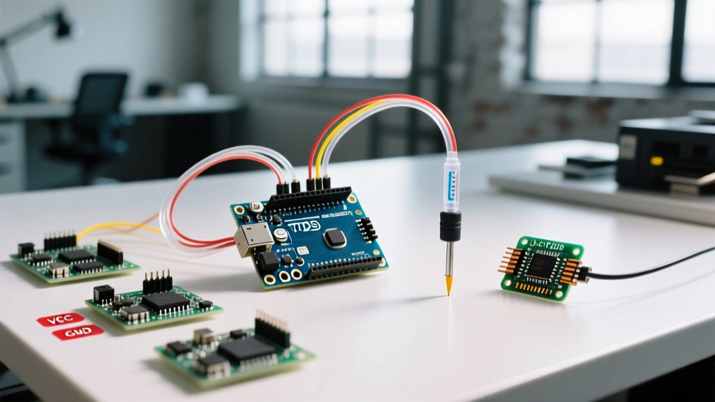

Total Dissolved Solids (TDS) measurement is a cornerstone of hydroponics, aquaculture, and water purification monitoring. Interfacing a TDS probe Arduino setup seems straightforward on the surface: read an analog pin and map the voltage to parts per million (PPM). However, makers and engineers frequently encounter drifting values, temperature-induced errors, and severe ADC noise. According to the USGS Water Science School, TDS represents the combined total of all inorganic and organic substances contained in a liquid, making precise measurement critical for biological and chemical stability.
This configuration guide bypasses basic tutorials to detail how to properly wire, calibrate, and temperature-compensate your TDS sensor for laboratory-grade reliability in 2026, utilizing modern microcontrollers and precision voltage references.
Hardware Teardown: DFRobot SEN0244 vs. Generic TS-10
Not all TDS modules are created equal. The market is dominated by two primary architectures: the premium DFRobot Gravity Analog TDS Sensor (SKU: SEN0244) and the generic, unbranded TS-10 modules found on bulk marketplaces.
| Feature | DFRobot SEN0244 (Gravity) | Generic TS-10 Module |
|---|---|---|
| Typical Price (2026) | $24.95 - $28.00 | $8.00 - $12.50 |
| Signal Conditioning | Onboard op-amp filtering & square wave driver | Basic voltage divider, prone to noise |
| Electrode Material | Stainless steel 316L, corrosion-resistant | Standard stainless steel, rapid degradation |
| Output Signal | 0 - 3.3V Analog (Linear to EC) | 0 - 5V Analog (Non-linear, noisy) |
| Waterproof Rating | IP68 (Potted electronics) | IP65 (Probe only, exposed PCB) |
For any deployment lasting longer than a weekend, the DFRobot SEN0244 is the mandatory choice. Its onboard signal conditioning circuit drives the probe with an AC square wave, preventing the electrolysis that destroys generic DC-driven probes. As detailed in the official DFRobot SEN0244 Wiki, this module outputs a clean analog voltage that correlates directly to Electrical Conductivity (EC), which is then mathematically converted to TDS.
Precision Wiring: Eliminating ADC Noise
The most common point of failure in a TDS probe Arduino configuration is relying on the microcontroller's default 5V USB rail as the Analog-to-Digital Converter (ADC) reference. USB voltage can fluctuate between 4.7V and 5.2V depending on the host port and cable quality. Because the ADC calculates voltage based on this reference, a 0.1V drop in USB power will cause your TDS readings to swing wildly by 50+ PPM.
The External VREF Solution
To achieve stable readings, you must decouple your analog reference from the noisy digital power supply.
- For Legacy Arduino Uno/Nano (ATmega328P): Do not use the 5V pin. Instead, use an external precision shunt regulator like the LM4040 (4.096V variant). Connect the LM4040 to the AREF pin, and use the
analogReference(EXTERNAL)function in your sketch. The Arduino analogReference documentation explicitly warns against using internal references without external stabilization for precision sensors. - For Arduino Uno R4 Minima / ESP32-S3: Modern boards feature 14-bit and 12-bit ADCs respectively, alongside dedicated 3.3V LDO regulators. Power the TDS module from the 3.3V pin and configure your software to map the ADC ceiling to 3.3V. The higher bit-depth (16,384 steps on the R4 vs 1,024 on the Uno) provides vastly superior resolution for detecting minor PPM shifts.
The Critical Role of Temperature Compensation
TDS is not measured directly; it is derived from Electrical Conductivity (EC). The conductivity of water is highly dependent on temperature. As water warms, ion mobility increases, causing the EC to rise even if the actual dissolved solid mass remains unchanged. Standard TDS probes are calibrated at 25°C. Without temperature compensation, a hydroponic nutrient solution at 18°C will read significantly lower than its true concentration, leading to fatal over-fertilization when the system warms up.
Engineering Rule of Thumb: The temperature coefficient ($\beta$) for most natural and agricultural water sources is approximately 0.02 to 0.025 per °C. This means EC changes by roughly 2% for every 1°C deviation from 25°C.
To implement this, you must pair your TDS probe with a digital temperature sensor like the DS18B20 immersed in the same solution. The compensation formula applied in your Arduino sketch must be:
EC_25 = EC_measured / (1 + beta * (Temperature - 25.0))
Only after calculating EC_25 should you apply the polynomial mapping to convert the voltage into PPM.
Step-by-Step Calibration Protocol
Factory calibration is rarely sufficient for precise agricultural or laboratory work. You must perform a two-point calibration using known buffer solutions.
Step 1: Zero-Point Calibration (Dry/Short)
- Ensure the TDS probe is completely dry and clean.
- Short the analog signal pin to GND (or read the dry probe, which should output near 0V).
- Record the raw ADC value. This is your zero-offset. Store this value in the microcontroller's EEPROM.
Step 2: Buffer Solution Calibration
- Acquire a standardized TDS calibration solution (e.g., 1000 PPM NaCl or KCl standard, available from lab supply stores for ~$15).
- Immerse the probe and the DS18B20 sensor into the solution. Stir gently to remove air bubbles trapped on the electrode surface.
- Wait exactly 120 seconds for the thermal mass of the probe to equalize with the liquid.
- Read the stabilized analog voltage. Using the known PPM of the buffer and the temperature-compensated voltage, calculate your specific calibration slope.
- Save the slope multiplier to EEPROM to survive power cycles.
Edge Cases: Preventing Electrolysis and Probe Degradation
A fatal mistake made by beginners is leaving the TDS probe powered continuously while submerged. If your specific module drives the probe with a DC voltage (common in cheap TS-10 clones), continuous power causes electrolysis. The water molecules split, and the metal electrodes rapidly oxidize and dissolve into the water, permanently ruining the probe and contaminating your sample.
The MOSFET Switching Fix:
Even if using a module that claims to use an AC square wave, best practice in industrial IoT design is to only power the sensor during the measurement window. Wire the VCC of the TDS module through a logic-level N-channel MOSFET (like the IRLZ44N) or a P-channel MOSFET (like the IRF9540N) controlled by a digital GPIO pin on your Arduino.
- Set GPIO HIGH to power the module.
- Wait 500ms for the op-amp and ADC sample-and-hold circuits to stabilize.
- Take 20 analog readings, discard the top and bottom 5, and average the middle 10.
- Set GPIO LOW to cut power completely.
This duty-cycling approach extends the lifespan of a $25 probe from a few months to several years, while also eliminating any residual heating of the water caused by the probe's internal circuitry.
Summary of Configuration Best Practices
Building a reliable TDS probe Arduino setup requires moving beyond simple analogRead() mappings. By investing in a square-wave driven sensor like the SEN0244, stabilizing your ADC with an external VREF, implementing rigorous DS18B20 temperature compensation, and duty-cycling the probe power via a MOSFET, you transform a noisy hobbyist circuit into a robust, deployment-ready water quality monitor.