
Decoding the Question: Arduino is What, Exactly?
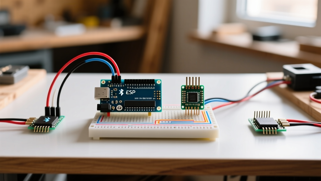
When makers and engineers ask, 'Arduino is what?', they are usually looking at a small blue or green circuit board and wondering how it translates into blinking lights, reading sensors, or controlling motors. The most accurate answer is that Arduino is not just a piece of hardware; it is a three-pillar ecosystem designed to abstract the complexities of bare-metal microcontroller programming.
- Pillar 1: The Silicon (Hardware) - Standardized development boards featuring microcontrollers (MCUs) with pre-routed power regulation, USB-to-serial interfaces, and exposed GPIO pins.
- Pillar 2: The Abstraction (Core Libraries) - A C++ framework that translates complex register-level hardware commands into simple functions like
digitalWrite()andanalogRead(). - Pillar 3: The Toolchain (IDE) - An integrated development environment that handles code compilation, library management, and firmware uploading via a single click.
In this 2026 how-to tutorial, we will move past the basic definitions and walk through the exact steps to select a modern board, configure your toolchain, and wire up a real-world I2C environmental sensor.
Step 1: Selecting Your 2026 Microcontroller Board
The classic Arduino Uno R3 (based on the 8-bit ATmega328P) is now considered legacy hardware. For modern projects, the ecosystem has shifted toward 32-bit ARM and Xtensa architectures. Below is a comparison of the current standard-bearers for beginners and intermediate makers.
| Board Model | Core MCU | Clock Speed | Flash / SRAM | 2026 MSRP | Best Use Case |
|---|---|---|---|---|---|
| Uno R4 Minima | Renesas RA4M1 (ARM Cortex-M4) | 48 MHz | 256 KB / 32 KB | $27.50 | Pure 5V logic learning, high-speed math, DSP |
| Uno R4 WiFi | Renesas RA4M1 + ESP32-S3 | 48 MHz / 240 MHz | 256 KB / 32 KB | $44.90 | IoT dashboards, wireless telemetry, LED matrices |
| Nano ESP32 | ESP32-S3 (Dual-core Xtensa) | 240 MHz | 8 MB / 512 KB | $21.00 | Space-constrained WiFi/BLE projects, audio processing |
Source: Hardware specifications and pricing verified via the Arduino Official Documentation and authorized 2026 distributor catalogs.
For this tutorial, we will use the Arduino Uno R4 Minima. Its 32-bit ARM Cortex-M4 processor offers a massive leap in floating-point math performance over the old 8-bit AVRs, making it ideal for processing raw sensor data without hardware bottlenecks.
Step 2: Installing the Modern Arduino IDE
The Java-based legacy IDE has been fully replaced by the modern Arduino IDE 2.3.x, built on an Electron frontend with a Go-based backend for vastly improved compilation speeds and IntelliSense code completion.
- Navigate to the Arduino Software Page and download the IDE 2.3.x installer for your OS (Windows 11, macOS Sonoma/Sequoia, or Ubuntu 24.04).
- During Windows installation, ensure you check the boxes for 'Install USB Drivers' and 'Associate .ino files'. Missing the Renesas CDC driver is the #1 cause of 'Port Grayed Out' errors on fresh builds.
- Launch the IDE, connect your Uno R4 Minima via a USB-C data cable (ensure it is not a charge-only cable), and navigate to Tools > Board > Arduino AVR Boards (or Renesas Arduino Boards depending on your core version) and select Arduino Uno R4 Minima.
- Verify the COM port is assigned under Tools > Port.
Step 3: Wiring a Real-World I2C Sensor (BME280)
Skip the basic 'Blink' sketch. To understand how Arduino interacts with the physical world, we will wire a BME280 Environmental Sensor (measuring temperature, humidity, and barometric pressure) using the I2C communication protocol.
Pro-Tip on I2C Pull-Up Resistors: The I2C protocol requires pull-up resistors on the SDA and SCL lines. While the Uno R4 has internal weak pull-ups, they are often insufficient for high-speed communication. Always use a BME280 breakout board (like those from Adafruit or SparkFun) that includes onboard 4.7kΩ surface-mount pull-up resistors to prevent data bus hanging.
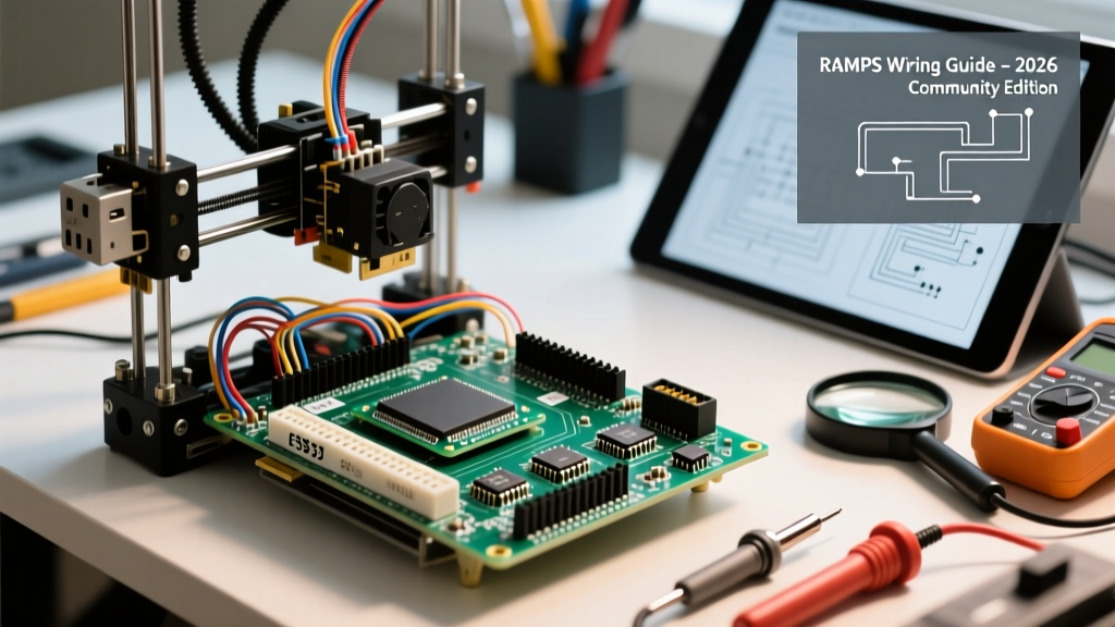
Wiring Diagram (Uno R4 Minima to BME280 Breakout)
- VIN / VCC → 5V Pin (The Uno R4 Minima's 5V rail is regulated and stable up to 800mA).
- GND → GND Pin.
- SCL → A5 (or the dedicated SCL header pin near the USB port).
- SDA → A4 (or the dedicated SDA header pin).
For a deeper dive into the sensor's internal architecture and calibration registers, refer to the Adafruit BME280 Learning Guide.
Step 4: Writing the Sketch and Managing Memory
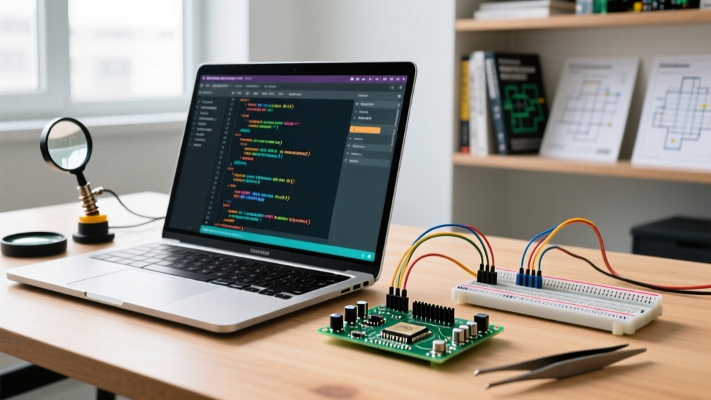
Open the Library Manager (Ctrl+Shift+I or Cmd+Shift+I) and install the Adafruit BME280 Library and its dependency, the Adafruit Unified Sensor Driver.
Copy the following code into your sketch:
#include <Wire.h>
#include <Adafruit_Sensor.h>
#include <Adafruit_BME280.h>

Adafruit_BME280 bme;

void setup() {
  Serial.begin(115200);
  while (!Serial) delay(10); // Wait for serial port to connect

  // Initialize I2C with specific address (0x76 or 0x77)
  if (!bme.begin(0x76)) {
    Serial.println(F('Could not find a valid BME280 sensor, check wiring!'));
    while (1) delay(10); // Halt execution to prevent I2C bus spam
  }
  Serial.println(F('BME280 initialized successfully.'));
}

void loop() {
  Serial.print(F('Temp: ')); Serial.print(bme.readTemperature()); Serial.println(F(' *C'));
  Serial.print(F('Humidity: ')); Serial.print(bme.readHumidity()); Serial.println(F(' %'));
  Serial.print(F('Pressure: ')); Serial.print(bme.readPressure() / 100.0F); Serial.println(F(' hPa'));

  delay(2000); // 2-second polling interval
}
Understanding Memory Constraints (Flash vs. SRAM)
When compiling this sketch, the IDE will report memory usage. The Uno R4 Minima has 256 KB of Flash (where your compiled code and string literals live) and 32 KB of SRAM (where variables and the heap reside). Using the F() macro around strings in your Serial.print() statements forces the compiler to keep those strings in Flash memory, preventing them from consuming your limited 32 KB SRAM at runtime. This is a critical habit for preventing heap fragmentation and random reboots in long-running deployments.
Step 5: Compilation, Upload, and Edge-Case Troubleshooting
Click the Upload button (the right-facing arrow). The IDE will compile the C++ code into ARM machine code via the GCC toolchain and push it over the USB-C CDC serial connection. If the upload succeeds, open the Serial Monitor (set to 115200 baud) to view your environmental data.
Troubleshooting Common Failure Modes
Even with a perfect setup, you may encounter hardware or software edge cases. Here is how to resolve the most common 2026 troubleshooting scenarios:
- Failure Mode 1: 'Port Grayed Out' or 'Upload Timeout'
Cause: The bootloader crashed or the CDC driver failed to enumerate.
Fix: Perform the 1200bps Reset Trick. Open the Serial Monitor, change the baud rate to exactly 1200, and close it. This specific baud rate signals the Renesas bootloader to reset the MCU and stay in programming mode. Alternatively, rapidly double-tap the physical red RESET button on the board to force bootloader mode, then click Upload. - Failure Mode 2: Serial Monitor Prints 'Could not find a valid BME280'
Cause: I2C address mismatch or missing pull-up resistors.
Fix: Some BME280 breakouts default to the I2C address0x77instead of0x76. Change the argument inbme.begin(0x77). If it still fails, use an I2C Scanner sketch to verify the bus is pulling high. If the scanner hangs, your SDA/SCL lines are missing the 4.7kΩ pull-up resistors mentioned in Step 3. - Failure Mode 3: Random Garbage Characters in Serial Monitor
Cause: Baud rate mismatch.
Fix: Ensure the baud rate dropdown in the top right corner of the Serial Monitor exactly matches theSerial.begin(115200)value in yoursetup()function.
Conclusion: From 'What is it?' to 'What can it do?'
Understanding 'Arduino is what' requires looking past the physical PCB and recognizing it as a standardized bridge between software logic and hardware physics. By selecting the right 32-bit architecture like the Uno R4 Minima, managing your SRAM effectively with the F() macro, and understanding the electrical requirements of protocols like I2C, you transition from a beginner copying tutorials to an embedded systems practitioner capable of deploying reliable, real-world telemetry nodes.