
Beyond the Basics: Configuring Sound Detector Arduino Circuits
Integrating a sound detector Arduino module into a project seems trivial until you encounter clipping, missed triggers, or overwhelming ambient noise floors. Most beginner tutorials treat microphone modules as simple binary switches, ignoring the analog nuances required for reliable acoustic sensing. Whether you are building a voice-activated relay, a decibel meter, or a glass-break detector, proper hardware selection, logic-level translation, and Analog-to-Digital Converter (ADC) configuration are mandatory for success in 2026's maker landscape.
This configuration guide dissects the two most prevalent microphone modules on the market—the budget-friendly KY-038 and the high-fidelity MAX9814—and provides exact calibration procedures, wiring schematics, and microcontroller-level ADC optimizations.
Hardware Selection: KY-038 vs. MAX9814
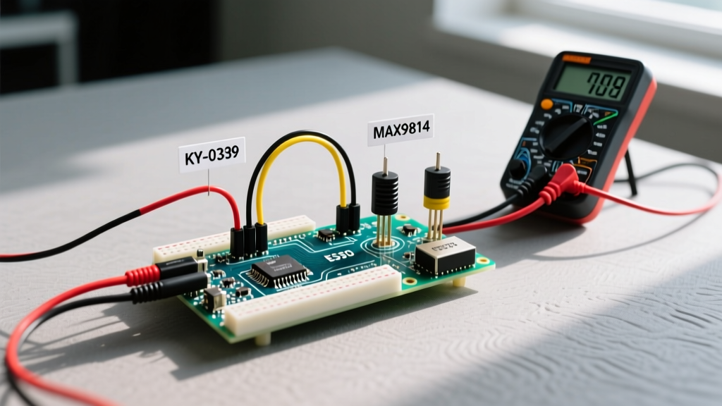
Choosing the correct sensor dictates your entire circuit topology. The KY-038 relies on an LM393 comparator for digital thresholding, while the MAX9814 utilizes an automatic gain control (AGC) amplifier for raw analog waveform capture.
| Specification | KY-038 (Standard Module) | Adafruit MAX9814 |
|---|---|---|
| Primary IC | LM393 Comparator + Electret | MAX9814 Mic Amp + Electret |
| Outputs | Analog (AO) & Digital (DO) | Analog Only (with DC Bias) |
| Gain Control | Manual (via physical trim pot) | Automatic (AGC) - Selectable 40/50/60dB |
| Typical 2026 Price | $1.20 - $2.50 USD | $8.50 - $12.00 USD |
| Best Use Case | Clap switches, loud noise triggers | Audio recording, FFT analysis, decibel metering |
Expert Insight: If your project requires analyzing the actual audio waveform (e.g., using Fast Fourier Transforms to detect specific frequencies), the KY-038's analog output is virtually useless due to its high noise floor and lack of biasing. You must use the MAX9814 or a similar amplified breakout board. For a deep dive into the MAX9814's internal AGC architecture, refer to the Analog Devices MAX9814 Datasheet.
Wiring and Logic Level Translation
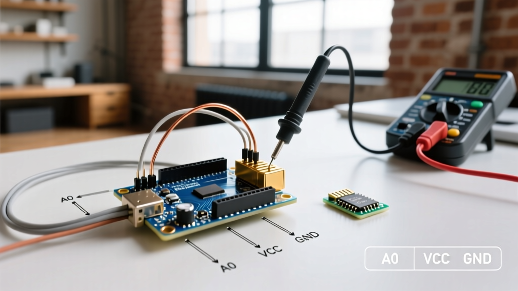
A common failure mode in modern sound detector Arduino setups involves frying the analog pins on 3.3V microcontrollers (like the ESP32-S3 or Raspberry Pi Pico RP2040) by feeding them 5V signals from a legacy KY-038 module.
3.3V vs 5V Configuration
- ATmega328P (Arduino Uno/Nano): Operates at 5V. Wire the module VCC directly to the 5V pin. The analog output will swing from 0V to 5V, perfectly matching the 10-bit ADC reference.
- ESP32 / RP2040: Operates at 3.3V. Power the KY-038 with 3.3V (it will function, though with slightly reduced sensitivity). If you must use 5V for the module, you must place a voltage divider (e.g., 10kΩ and 22kΩ resistors) on the AO and DO pins to step the 5V output down to a safe ~3.2V before it hits the MCU GPIO.
For the MAX9814, the output is biased at VCC/2. If powered by 3.3V, the idle output sits at 1.65V, swinging ±1.65V. This is perfectly safe for 3.3V ADC pins and eliminates the need for external DC blocking capacitors. For comprehensive wiring diagrams, the Adafruit Microphone Amplifier Breakout Guide provides excellent visual references.
Calibrating the LM393 Threshold (Digital Output)
The KY-038 features a blue trimpot that sets the trigger threshold for the Digital Out (DO) pin. Factory calibration is almost never suitable for real-world environments. Follow this precise calibration sequence:
- Establish the Noise Floor: Upload a blank sketch with the Serial Monitor open. Ensure the room is in its typical 'quiet' state (HVAC running, ambient street noise).
- Monitor the DO Pin: Read the digital pin state continuously. If the serial monitor prints '1' (or HIGH) continuously, the threshold is too low.
- Adjust the Trimpot: Using a precision ceramic screwdriver (to avoid altering the inductance or capacitance of the circuit with metal tools), turn the potentiometer clockwise until the DO pin reads '0' (LOW).
- Set the Hysteresis Margin: Turn the pot slightly back (counter-clockwise) until it just barely flickers to HIGH, then back to LOW. This sets the trigger point exactly 2-3 dB above your ambient noise floor.
- Lock the Pot: Apply a micro-drop of non-conductive nail polish or Loctite 430 (cyanoacrylate) to the screw head to prevent mechanical vibration from shifting the wiper over time.
Optimizing the ATmega328P ADC for Audio (Analog Output)
When using the analog output of a sound detector Arduino setup, the default configuration of the ATmega328P is woefully inadequate for audio frequencies. By default, the Arduino IDE sets the ADC prescaler to 128.
The Math Behind the Bottleneck
The ATmega328P runs at 16 MHz. With a prescaler of 128, the ADC clock is 125 kHz. Since a single 10-bit conversion takes 13 ADC clock cycles, the maximum sampling rate is roughly 9.6 kHz. According to the Nyquist-Shannon sampling theorem, a 9.6 kHz sampling rate can only accurately reproduce frequencies up to 4.8 kHz—completely missing the higher harmonics of human speech and glass-breaking frequencies.
Overriding the Prescaler
To capture higher audio frequencies, you must lower the prescaler. The ATmega328P datasheet states that the ADC clock should ideally be between 50 kHz and 200 kHz for maximum 10-bit resolution, but pushing it to 1 MHz (prescaler of 16) yields a sampling rate of ~76.8 kHz with only a minor drop in precision (effective 8-9 bits), which is perfectly acceptable for acoustic envelope detection.
Insert this bitwise configuration in your setup() loop before calling analogRead():
// Clear the ADPS0, ADPS1, and ADPS2 bits in the ADCSRA register
ADCSRA &= ~(bit (ADPS0) | bit (ADPS1) | bit (ADPS2));

// Set the prescaler to 16 (16MHz / 16 = 1MHz ADC Clock)
ADCSRA |= bit (ADPS2);
Note: For standard Arduino syntax and register manipulation rules, always consult the official Arduino Analog I/O Documentation.
Real-World Failure Modes and Edge Cases
Even with perfect code, physical and environmental factors will break your sound detector Arduino implementation if not mitigated.
| Failure Mode | Symptom | Engineering Solution |
|---|---|---|
| Microphonic Feedback / Handling Noise | Sensor triggers when the enclosure is tapped or bumped, not just from airborne sound. | Suspend the microphone module using closed-cell foam or silicone grommets. Never hard-mount the PCB directly to a vibrating chassis. |
| Ground Loop Hum (50/60Hz) | Analog readings show a massive, rhythmic sine wave even in silence. | Ensure the microphone module shares a common, star-grounded GND plane with the MCU. Avoid powering the module from a noisy switching buck converter; use an LDO regulator. |
| ADC Clipping on ESP32 | Loud sounds read as a flatline maximum value (4095), destroying waveform data. | The ESP32 ADC is non-linear near the rails (above 3.1V). Bias the MAX9814 to 1.5V instead of 1.65V, or reduce the module's hardware gain jumper from 60dB to 50dB. |
| Wind / Air Current Saturation | Constant false triggers in outdoor or drafty environments. | Fit a dense acoustic windscreen (deadcat) or 3D print a labyrinthine acoustic housing to disrupt low-frequency wind pressure while allowing high-frequency sound to pass. |
Advanced Configuration: Envelope Detection via Software
If you are using the analog output to detect loud events (rather than raw audio recording), reading raw ADC values is inefficient. Instead, implement a software envelope follower. This involves tracking the peak amplitude over a short window (e.g., 10ms) and applying an exponential decay. This mimics the behavior of analog peak detector circuits and drastically reduces the processing load on your MCU, allowing you to run complex motor controls or network tasks simultaneously without missing acoustic triggers.
Frequently Asked Questions
Can I use the KY-038 to record voice audio?
No. The KY-038 lacks the necessary biasing and amplification bandwidth for intelligible voice recording. It is strictly a threshold-trigger device. Use an I2S MEMS microphone (like the INMP441) or the MAX9814 for voice applications.
Why does my analogRead() return 0 on the MAX9814?
The MAX9814 outputs a DC biased signal (usually VCC/2). If you are using AC coupling capacitors on the breadboard and the capacitor is oriented incorrectly or is too small (use at least 1µF ceramic), the signal will be blocked. Furthermore, ensure you are not accidentally reading a digital pin assigned to the analog channel.
How do I protect the microphone from water damage in outdoor projects?
Apply a breathable, hydrophobic acoustic membrane (such as Gore-Tex acoustic vents) over the microphone port. Do not coat the electret capsule itself in conformal coating or epoxy, as this will physically dampen the diaphragm and destroy its sensitivity.