
The Core Challenge: Navigating RS485 Arduino Ecosystems
Integrating industrial communication protocols into hobbyist microcontrollers is a rite of passage for advanced makers. When building long-distance sensor networks, motor controllers, or Modbus RTU devices, the RS-485 standard is the undisputed king. However, achieving seamless RS485 Arduino compatibility is rarely as simple as plugging in a module and uploading a sketch. The primary friction point lies in the collision between legacy 5V logic and modern 3.3V microcontrollers, compounded by hardware flow-control nuances and termination requirements.
According to the Texas Instruments RS-485 design guidelines, the standard supports data rates up to 10 Mbps and cable lengths exceeding 1,200 meters. But to achieve these metrics in a maker environment, you must match the correct transceiver IC to your specific Arduino board's logic level and UART capabilities. This guide dissects the hardware compatibility matrix, wiring topologies, and software configurations required to build bulletproof RS-485 networks in 2026.
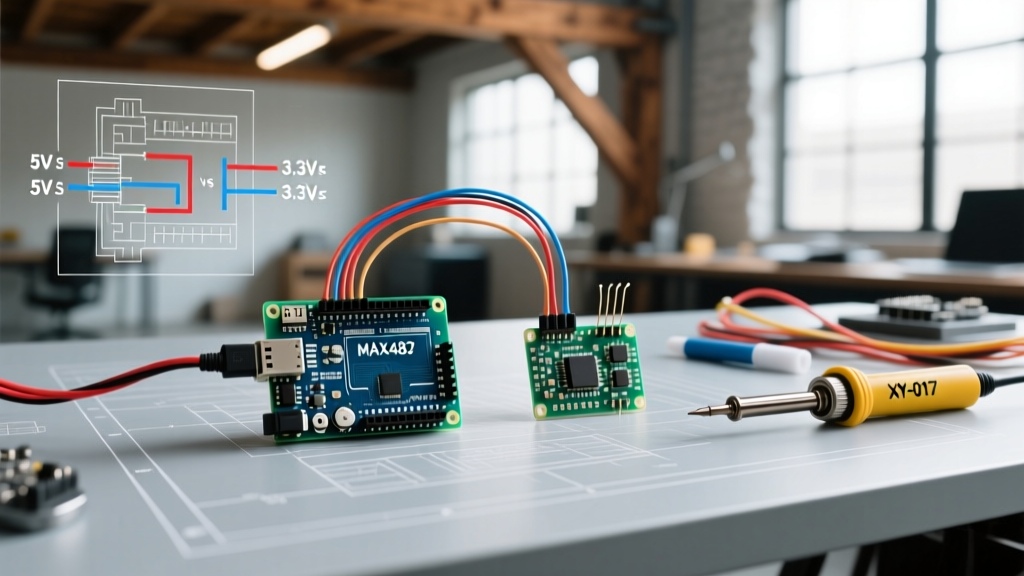
The Voltage Trap: 5V vs 3.3V Logic Levels
The most common point of failure in RS485 Arduino projects is logic level mismatching. The classic Arduino Uno, Nano, and Mega 2560 operate at 5V logic. Conversely, modern powerhouses like the ESP32, Raspberry Pi Pico (RP2040), and Adafruit Feather SAMD boards operate strictly at 3.3V.
CRITICAL WARNING: Feeding the 5V TX/RX output of a standard MAX485 module directly into a 3.3V ESP32 GPIO pin will permanently damage the microcontroller's silicon. Always verify your transceiver's VCC and logic threshold requirements before applying power.
While a 3.3V board might successfully read a 5V signal as HIGH (since 3.3V exceeds the typical 2.0V TTL HIGH threshold), the 3.3V output from the microcontroller may fail to trigger the 5V transceiver's input, resulting in silent transmission failures or corrupted packets.
RS485 Arduino Module Compatibility Matrix
The market is flooded with TTL-to-RS485 adapter boards. Below is a compatibility matrix detailing the most common modules, their underlying ICs, and their ideal microcontroller pairings. Pricing reflects average market rates from major electronics distributors like DigiKey and AliExpress in early 2026.
| Module Name | Core IC | Logic Voltage | Auto-Direction | Avg. Price | Best Paired With |
|---|---|---|---|---|---|
| HW-519 (Red) | MAX485 | 5V Only | No (Manual DE/RE) | $1.50 | Uno, Mega, Nano |
| XY-017 | SP485 / SP3485 | 3.3V - 5V | Yes (Hardware) | $3.50 | ESP32, RP2040, STM32 |
| Isolated RS485 | MAX3485 + ADUM1201 | 3.3V - 5V | Yes (Hardware) | $8.50 | Industrial/Noisy environments |
| UART to RS485 (TTL) | MAX3485 | 3.3V Only | No (Manual DE/RE) | $2.00 | ESP8266, SAMD21 |
Deep Dive: Why the XY-017 is the 2026 Standard
For mixed-voltage environments, the XY-017 module has largely replaced the legacy red MAX485 boards. It features an onboard hardware flow-control circuit utilizing a small array of transistors and resistors that automatically toggle the DE (Driver Enable) and RE (Receiver Enable) pins based on the UART TX line state. This eliminates the need for software-based GPIO toggling, freeing up processing cycles and drastically reducing timing errors in high-baud-rate Modbus RTU implementations.
Wiring Topologies and Termination Resistors
The Wikipedia RS-485 standard documentation emphasizes that RS-485 is a differential signaling protocol. It measures the voltage difference between the A and B lines, making it highly immune to common-mode noise. However, this immunity relies on proper physical layer implementation.
The Mandatory Common Ground
A pervasive myth in maker forums is that RS-485 only requires two wires (A and B). While the differential signal travels over these two wires, the transceivers require a common ground reference to keep the common-mode voltage within the IC's acceptable range (typically -7V to +12V). Without a shared ground wire, ground potential differences between distant nodes will saturate the receiver, leading to total bus lockups.
Termination and Biasing: A Step-by-Step Approach
To prevent signal reflections that corrupt data at baud rates above 19,200, you must implement proper termination and biasing. Follow this checklist for a multi-drop bus:
- Twisted Pair Cabling: Use a shielded twisted pair (STP) cable. Belden 9841 is the industry standard, but standard Cat5e Ethernet cable works exceptionally well for runs under 100 meters.
- Termination Resistors: Solder a 120-ohm resistor between the A and B terminals at the first and last physical nodes on the bus. Do not place termination resistors on intermediate nodes.
- Biasing Resistors: On the master node (usually the Arduino), connect a 560-ohm pull-up resistor from the A line to VCC (5V/3.3V), and a 560-ohm pull-down resistor from the B line to GND. This ensures the bus sits in a known 'MARK' (idle) state when no device is transmitting, preventing phantom characters from floating noise.
Library Compatibility and Sketch Management
Hardware compatibility is only half the battle; software management dictates the reliability of your RS485 Arduino network. The choice between HardwareSerial and SoftwareSerial heavily influences your maximum reliable baud rate.
- Hardware UART (Serial1, Serial2, etc.): Always use hardware UART pins when possible. Boards like the Arduino Mega (4 UARTs) and ESP32 (3 UARTs) allow you to dedicate a hardware serial port to the RS-485 bus. This offloads timing to the silicon, supporting baud rates up to 115,200 without dropped bytes.
- SoftwareSerial / AltSoftSerial: If you are forced to use an Arduino Uno (which only has one hardware UART, shared with the USB debugger), you must use software emulation. Standard
SoftwareSerialblocks interrupts and fails reliably above 38,400 baud. Use theAltSoftSeriallibrary instead, which utilizes hardware timers for more accurate bit-banging, capping out safely at 57,600 baud.
For protocol management, the ModbusMaster library remains the gold standard for Arduino-based Modbus RTU masters. If you are building a custom, non-Modbus packet structure, the RS485_protocol library provides excellent CRC-16 validation and framing tools.
Real-World Failure Modes and Troubleshooting
Even with perfect wiring, RS-485 networks can exhibit erratic behavior. Here are the most common edge cases and their solutions:
1. The Floating DE/RE Pin Trap
If you are using a manual module (like the HW-519) and forget to define the DE/RE pins in your sketch, or if the GPIO pin is left in a high-impedance state during boot, the module may default to transmit mode. This will jam the entire bus. Fix: Always use internal pull-down resistors in your setup() function or wire a physical 10k pull-down resistor on the DE/RE line to ensure the bus defaults to Receive mode on boot.
2. Ground Loop Destruction
In environments with heavy AC motors or VFDs (Variable Frequency Drives), connecting the Arduino's digital ground to the RS-485 shield can create a ground loop, inducing high currents that fry the transceiver. Fix: Use an isolated RS-485 module featuring digital isolators (like the ADUM1201) and an isolated DC-DC power supply for the bus side of the transceiver.
3. Direction Switching Latency
When using manual DE/RE control via software, makers often fail to wait for the final byte to clear the hardware shift register before pulling the DE pin LOW. This cuts off the last few bits of the final byte, causing CRC failures on the receiving end. Fix: Use the Serial.flush() command before toggling the DE pin back to Receive mode, ensuring the TX buffer is entirely empty and the final stop-bit has been transmitted onto the wire.