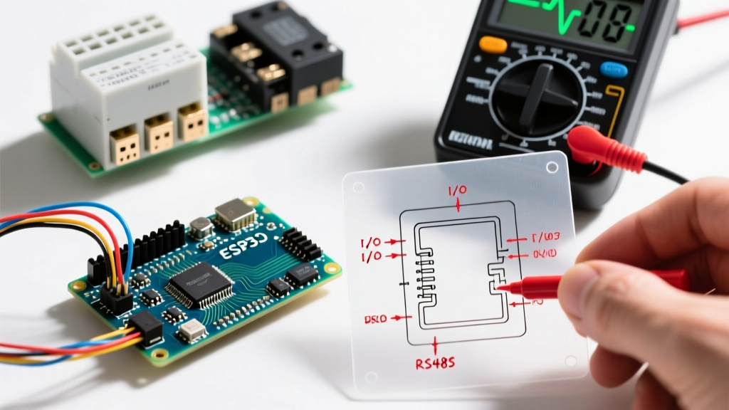

The Industrial Shift: Arduino PLC Controllers in the Field
The transition from hobbyist microcontrollers to industrial automation has made the arduino plc controller a staple in modern manufacturing and building management systems. Devices like the official Arduino Opta (powered by the STM32H747XI dual-core processor) and the Controllino MAXI have bridged the gap between accessible programming and rugged 24VDC industrial environments. However, deploying these devices on the factory floor introduces electrical noise, grounding loops, and protocol mismatches that standard breadboard setups never face.
As of 2026, the Arduino PLC IDE and IEC 61131-3 compliant ladder logic environments have matured significantly, but hardware-level troubleshooting remains a critical skill. This guide provides deep-dive diagnostics for the most common field failures encountered when deploying an arduino plc controller, focusing on I/O protection, RS485 communication, and firmware lockups.
Quick Diagnostic Matrix: Arduino PLC Controller Faults
Before diving into multimeter probes and oscilloscopes, use this matrix to identify the root cause of your system's failure based on primary symptoms.
| Symptom | Probable Cause | Quick Field Fix |
|---|---|---|
| Relay output chatters or clicks rapidly | Inductive kickback from solenoids/contactors lacking flyback diodes | Install 1N4007 diode or RC snubber across the load |
| RS485 Modbus RTU timeouts | Missing termination resistors or A/B line swap | Add 120Ω termination; verify polarity with multimeter |
| 4-20mA analog input reads erratic | Ground loop or missing 250Ω shunt resistor | Verify isolated PSU; measure shunt voltage (1-5V) |
| PLC IDE upload fails / Bootloop | Watchdog Timer (WDT) triggering during boot | Disable WDT in code; use PLC IDE safe-mode recovery |
| Digital inputs trigger randomly | Capacitive coupling from adjacent high-voltage AC lines | Reroute cables; add 10kΩ pull-down resistors |
Fixing Digital I/O and Relay Chatter
When an arduino plc controller is used to switch inductive loads like 24VDC solenoid valves or motor contactors, the sudden collapse of the magnetic field generates a massive reverse voltage spike (inductive kickback). This spike can exceed 100V, easily breaching the internal optocouplers or solid-state relays (SSRs) of the PLC.
Hardware Protection Strategies
- Electromechanical Relays (e.g., Controllino): Always wire a flyback diode (like a 1N4007) in reverse parallel across the inductive load. The cathode (stripe) must face the positive 24VDC supply.
- Solid-State Relays (e.g., Arduino Opta): The Opta utilizes electromechanical relays for its 4 isolated outputs, but if you are driving external SSRs, ensure the SSR has a built-in snubber circuit. If not, wire an RC snubber (typically 100Ω in series with a 0.1µF capacitor) across the load terminals.
Expert Insight: If your PLC's output LED is dimly lit even when the logic state is LOW, you are likely experiencing leakage current through long cable runs acting as capacitors. Adding a 10kΩ bleeder resistor between the output terminal and 0V (ground) will drain this parasitic capacitance.
Resolving RS485 Modbus RTU Communication Drops
RS485 is the backbone of industrial sensor networks, but it is highly susceptible to reflections and common-mode noise if the physical layer is improperly configured. According to the Modbus Organization Protocol Specifications, a standard RS485 network can span up to 1,200 meters and support 32 unit loads, but only if the electrical parameters are strictly maintained.
Step-by-Step RS485 Troubleshooting
- Verify Termination Resistors: The first and last devices on the RS485 daisy chain MUST have a 120Ω resistor connected between the A (D+) and B (D-) lines. Intermediate nodes must not have this resistor. Use a multimeter to measure resistance across the lines with power off; it should read roughly 60Ω if two 120Ω terminations are present at the ends.
- Check Biasing Resistors: If the network goes completely silent, the receiver might be floating in an undefined state. Install a 470Ω pull-up resistor from the A line to 5V/VCC, and a 470Ω pull-down resistor from the B line to GND on the master node.
- Inspect Galvanic Isolation: Industrial environments often have different ground potentials across a facility. If your arduino plc controller shares a ground with a VFD (Variable Frequency Drive), ground loops will corrupt the Modbus packets. Use an isolated RS485 transceiver (like the ISO3082) or an external DIN-rail RS485 isolator module (costing roughly $35-$50 USD) between the PLC and the field devices.
Analog Input Noise and 4-20mA Loop Troubleshooting
Many industrial sensors (pressure transmitters, flow meters) output a 4-20mA current loop. The Arduino Opta features dedicated analog inputs that can read voltage (0-10V) or current (4-20mA) via internal DIP switches or software configuration. However, noise from adjacent 3-phase power lines can induce significant drift.
Stabilizing 4-20mA Readings
If your PLC is configured for voltage reading but you are using a 4-20mA sensor, you must install an external precision 250Ω shunt resistor across the analog input and the analog ground. This converts the 4-20mA signal into a 1-5V signal. If your readings are jumping by 5-10%, the issue is almost always electromagnetic interference (EMI).
- Cable Routing: Never run 4-20mA analog cables in the same conduit as 480V AC motor cables. Maintain a minimum separation of 12 inches, or use grounded metallic dividers.
- Shielding: Use twisted-pair shielded cable (Belden 3105A or equivalent). Crucially, ground the shield at ONE end only (preferably at the PLC cabinet ground bus). Grounding both ends creates a ground loop that will inject 50/60Hz hum directly into your analog readings.
Overcoming PLC IDE and Firmware Lockups
Programming an arduino plc controller differs from standard hobbyist workflows. The Arduino PLC IDE Documentation outlines the use of IEC 61131-3 languages (Ladder, FBD, ST). A common catastrophic failure in field deployments is the Watchdog Timer (WDT) bootloop.
The Watchdog Timer Trap
In industrial PLCs, a hardware watchdog is often enabled by default to reset the CPU if the main logic loop hangs (e.g., waiting indefinitely for a Modbus response). If your ladder logic takes longer than the WDT timeout (often 2-4 seconds) to execute a single scan, the PLC will reset endlessly, preventing you from uploading new code.
The Fix: To recover a bricked Arduino Opta or similar controller trapped in a WDT bootloop, you must enter the bootloader safe mode. For the Opta, press and hold the BOOT0 button (or use the physical PLC IDE recovery sequence via USB-C) while applying power. This bypasses the user application and halts the WDT, allowing the PLC IDE to push a corrected firmware payload. Always include a WDT reset function (e.g., wdt_reset() or equivalent PLC IDE block) at the very end of your main cyclic task to prevent this in production.
Power Supply and Grounding Edge Cases
Do not power an industrial arduino plc controller with cheap, unregulated wall adapters. Industrial controllers require clean, regulated 24VDC. A high-quality DIN-rail power supply, such as the Mean Well HDR-30-24 (typically priced around $25-$30 USD), provides the necessary transient protection and stable voltage rails.
Furthermore, implement a star grounding topology inside your control panel. Connect the PLC ground, the 24VDC PSU ground, and the cable shields to a single, centralized copper ground busbar tied to the panel's earth ground. Avoid 'daisy-chaining' grounds from one device to the next, as the voltage drop across the wire resistance will create differing ground potentials, leading to erratic digital input triggering and analog noise.
By systematically addressing inductive kickback, RS485 termination, analog shielding, and watchdog configurations, you can ensure your arduino plc controller operates with the same reliability as traditional, high-cost automation hardware. For deeper hardware schematics and pinout configurations, always refer to the official device documentation before wiring your control cabinet.