
Scaling Your Arduino Stoplight: From Breadboard to Driveway
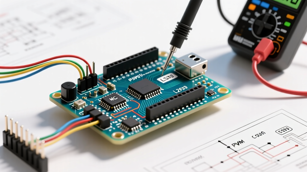
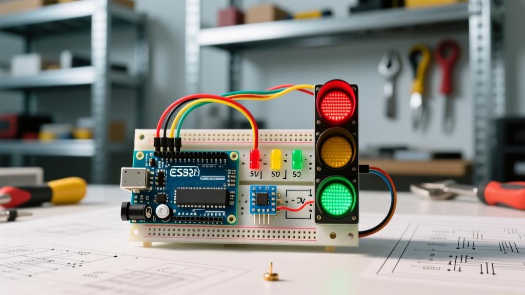
Building an arduino stoplight is a rite of passage for embedded systems hobbyists, but the leap from a simple educational breadboard model to a functional, outdoor-rated driveway replica introduces severe hardware compatibility challenges. The core issue is rarely the C++ sketch; it is the electrical mismatch between microcontroller logic levels, LED forward voltages, and high-current switching requirements. In 2026, with the widespread adoption of 3.3V microcontrollers and high-density addressable LEDs, understanding component interoperability is critical to preventing blown GPIO pins and erratic timing sequences.
This compatibility guide breaks down the exact hardware pairings required to build a robust traffic light system, detailing specific microcontroller models, illumination hardware, and isolation components.
The Logic Level Trap: 5V vs. 3.3V Microcontrollers
The most frequent point of failure in modern MCU projects is the logic level mismatch. Legacy Arduino boards operate at 5V, while modern Wi-Fi-enabled boards operate at 3.3V. If you attempt to drive a standard 5V optical-isolated relay module using an ESP32, the 3.3V HIGH signal will often fail to trigger the internal optocoupler, leaving your stoplight permanently dark or stuck on red.
Microcontroller Compatibility Matrix
| Microcontroller Board | Logic Level | Max Continuous I/O | Best Stoplight Application | Approx. Price (2026) |
|---|---|---|---|---|
| Arduino Uno R4 Minima | 5V | 14 Digital / 6 Analog | Single intersection, 5V relays, standard LEDs | $27.00 |
| Arduino Nano Every | 5V | 14 Digital / 8 Analog | Compact enclosures, breadboard prototyping | $11.50 |
| ESP32-S3 DevKitC | 3.3V | 45 GPIO | Networked smart intersections, requires level shifting | $8.00 |
| Arduino Mega 2560 | 5V | 54 Digital / 16 Analog | Multi-intersection city grid dioramas | $38.00 |
Expert Insight: If you choose the ESP32-S3 for its Wi-Fi capabilities to sync multiple stoplights via MQTT, you must use a logic level converter (like the BSS138 bidirectional shifter) or purchase specialized 3.3V-trigger relay modules. Standard logic level tutorials emphasize that feeding 5V back into a 3.3V ESP32 GPIO pin without a voltage divider will permanently destroy the silicon.
Illumination Hardware Pairings
The physical scale of your arduino stoplight dictates your LED architecture. You cannot power outdoor 12V LED clusters directly from an Arduino's 5V/40mA GPIO pins. Here is how to match your light source to the correct driver circuitry.
1. Breadboard Scale: Standard 5mm T1-3/4 Diffused LEDs
For desktop models, standard 5mm LEDs are ideal. However, you must calculate current-limiting resistors based on the specific forward voltage (Vf) of each color to ensure uniform brightness and prevent GPIO overcurrent.
- Red LED: Vf = 2.0V, Target Current = 20mA. On a 5V Uno, use a 150Ω resistor.
- Yellow LED: Vf = 2.1V, Target Current = 20mA. Use a 150Ω resistor.
- Green LED: Vf = 3.2V, Target Current = 20mA. Use a 91Ω resistor (or standard 100Ω).
Failure Mode: Wiring LEDs in parallel with a single shared resistor causes current hogging, where the LED with the lowest Vf hogs the current and burns out. Always use one resistor per LED.
2. Desktop Scale: WS2812B Addressable Modules
If you want dynamic fade effects or countdown timers inside the stoplight lenses, WS2812B (NeoPixel) rings are the best choice. These operate at 5V and require a precise 800kHz data signal.
Compatibility Warning: WS2812B LEDs are strictly incompatible with standard
analogWrite()PWM. You must use the Adafruit NeoPixel library. Furthermore, the ESP32's dual-core architecture can cause interrupt-driven timing glitches with WS2812B data streams. When using an ESP32, assign the NeoPixel data pin to a GPIO connected to the main core, or utilize the hardware RMT peripheral via the Adafruit NeoPixel Uberguide ESP32-specific fork.
3. Outdoor/Replica Scale: 12V High-Power LED Clusters
For driveway replicas using 12V automotive-style LED clusters (drawing 500mA to 2A per color), you must use N-Channel MOSFETs as low-side switches. Do not use the IRF520 MOSFET. Despite being sold in many 'Arduino relay kits', the IRF520 requires a 10V gate-to-source voltage to fully open. An Arduino's 5V output will leave it partially conducting, causing it to overheat and fail.
The Correct Component: Use the IRLZ44N or FQP30N06L. These are 'logic-level' MOSFETs with a gate threshold voltage (Vgs) of 1V to 2V, meaning they will fully saturate and conduct high current safely when driven by a 5V Arduino Uno or even a 3.3V ESP32. Always place a 10kΩ pull-down resistor between the Gate and Source to prevent the stoplight from turning on during MCU boot-up when GPIO pins are floating.
Relay Isolation and Flyback Protection
If your stoplight uses actual 120V AC incandescent bulbs or heavy inductive loads, mechanical relays are required. When a relay coil is de-energized, the collapsing magnetic field generates a high-voltage reverse spike (back-EMF) that can fry your microcontroller's voltage regulator.
The Isolation Checklist
- Optocoupler Integration: Use a PC817 optocoupler between your Arduino GPIO and the relay transistor base. This provides galvanic isolation, ensuring high-voltage spikes never reach your $27 microcontroller.
- Flyback Diode: Solder a 1N4007 rectifier diode in reverse bias across the relay coil terminals (cathode to 5V, anode to the transistor collector).
- Separate Power Rails: Never power 5V mechanical relay coils directly from the Arduino's onboard 5V regulator. The inrush current will cause brownouts, resetting your stoplight sketch mid-cycle. Use a dedicated 5V buck converter (like the LM2596) to power the relay VCC.
Edge Cases: Camera Flicker and PWM Frequency
A highly specific edge case in arduino stoplight builds occurs when the stoplight is filmed by dashcams, security cameras, or smartphones. Standard Arduino analogWrite() operates at roughly 490Hz. Because cameras use rolling shutters, a 490Hz PWM signal will cause severe visual banding and flickering on video, making the stoplight appear broken or strobing.
The Fix: You must increase the PWM frequency above the camera's shutter threshold (typically >20kHz). On an ATmega328P (Uno/Nano), you can manipulate Timer1 registers in your setup() function to push the PWM frequency on pins 9 and 10 to 31,372Hz. This completely eliminates camera flicker while maintaining smooth dimming transitions for yellow caution states.
Voltage Drop in Long Wire Runs
When mounting a stoplight on a 12-foot pole, the wire gauge becomes a critical compatibility factor. Pushing 12V at 1.5A through 24 feet of round-trip 22 AWG breadboard wire results in a voltage drop of over 1.5V. Your 12V LED clusters will receive only 10.5V, resulting in dim output and potential color shifting in RGB modules.
Specification Rule: For any outdoor arduino stoplight run exceeding 5 feet, use a minimum of 18 AWG stranded copper wire for the 12V power and ground lines. Keep the data lines (if using addressable LEDs) twisted with a ground wire to prevent electromagnetic interference from nearby AC mains or radio frequencies.
Summary Hardware BOM for a Standard 12V Replica
To guarantee compatibility and avoid the most common maker pitfalls, source the following exact components for a robust 12V single-intersection stoplight:
- MCU: Arduino Nano Every (5V logic, compact, $11.50)
- Switching: 3x IRLZ44N Logic-Level MOSFETs ($1.50 each)
- Gate Protection: 3x 10kΩ pull-down resistors, 3x 100Ω gate series resistors
- Power Supply: 12V 5A Switching Power Supply (Mean Well LRS-60-12, $18.00)
- Wiring: 18 AWG Stranded Silicone Wire for main power, 22 AWG for gate signals
By respecting logic levels, selecting the correct MOSFET gate thresholds, and isolating inductive loads, your arduino stoplight will transition from a fragile desk toy to a reliable, long-lasting embedded system. For deeper architectural schematics, always refer to the official Arduino hardware documentation to verify pinout tolerances before applying external power.