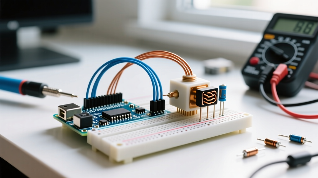

Interfacing a solenoid valve Arduino circuit is a rite of passage for makers building automated irrigation systems, fluid dispensers, or pneumatic controllers. On paper, the schematic looks trivial: a digital I/O pin, a switching transistor, and a 12V power supply. In practice, solenoids are highly inductive loads that generate severe electrical noise and voltage spikes. If your microcontroller keeps resetting, your transistor is melting, or the valve chatters erratically, you are dealing with classic inductive load failure modes.
As of 2026, modern logic-level MOSFETs and isolated optocouplers have made these circuits safer, but fundamental physics remains unchanged. This guide bypasses basic code debugging and dives straight into hardware error diagnosis, providing exact multimeter measurements, component replacements, and wiring corrections to get your solenoid valve Arduino project running reliably.
Error 1: The Arduino Resets or Dies Instantly Upon Switching
The Symptom: The moment your sketch pulls the gate pin LOW to turn off the solenoid, the Arduino reboots, freezes, or the ATmega328P chip is permanently bricked.
The Root Cause: Inductive kickback (Back-EMF). When current flows through the solenoid coil, it builds a magnetic field. When the MOSFET switches off, the magnetic field collapses rapidly. According to Faraday's law of induction ($V = -L \frac{di}{dt}$), this collapse induces a massive voltage spike—often exceeding 100V to 300V—in the reverse direction. This spike arcs across the MOSFET or travels back through the power rails, destroying the Arduino's 5V voltage regulator or the I/O pin itself.
The Fix: You must install a flyback (freewheeling) diode. According to DigiKey's technical guidelines on inductive loads, the diode must be placed in parallel with the solenoid coil, with the cathode (stripe) facing the positive voltage supply.
- Standard On/Off Valves: Use a 1N4007 rectifier diode (costs ~$0.10). It handles 1A continuous and 1000V peak inverse voltage (PIV), which is more than enough for standard 12V brass water valves.
- Wiring Check: Ensure the diode is physically located at the solenoid terminals, not back at the breadboard. Long wires between the diode and the coil act as antennas, allowing EMI to escape.
Error 2: Solenoid Chatters, Buzzes, or Only Partially Opens
The Symptom: The valve emits a loud 60Hz/120Hz buzzing sound, fails to pull the plunger fully open, or fluid flow is severely restricted despite the Arduino pin reading HIGH.
The Root Cause: Insufficient gate drive voltage or excessive voltage drop across the switching component. Many legacy tutorials recommend the TIP120 Darlington BJT. While the TIP120 can handle high currents, it has a massive collector-emitter saturation voltage ($V_{CE(sat)}$) of roughly 2.0V to 2.5V. If you are driving a 12V solenoid, the valve only receives 9.5V. Furthermore, if your 12V power supply sags under the initial inrush current (which can be 3x the holding current), the voltage drops below the solenoid's pull-in threshold, causing it to chatter.
The Fix: Abandon Darlington BJTs for solenoid switching. Upgrade to a Logic-Level N-Channel MOSFET like the IRLZ44N (~$1.50). Unlike standard MOSFETs, the IRLZ44N has an $R_{DS(on)}$ of just 22mΩ when driven at 5V from an Arduino. This results in a voltage drop of less than 0.05V, delivering the full 12V to the valve and eliminating chatter.
Error 3: The MOSFET Overheats or Melts Within Seconds
The Symptom: The switching transistor becomes too hot to touch within 10 seconds of the valve opening, eventually desoldering itself or shorting out.
The Root Cause: Using a standard-level MOSFET instead of a logic-level MOSFET. The IRF520 is a classic beginner mistake. It requires a Gate-to-Source voltage ($V_{GS}$) of 10V to fully turn on and achieve its rated low resistance. The Arduino outputs only 5V (or 3.3V on modern RP2040/ESP32 boards). At 5V, the IRF520 operates in its linear (ohmic) region, acting as a high-value resistor rather than a closed switch. It dissipates massive amounts of power as heat ($P = I^2R$).
The Fix & Diagnostic Step:
- Set your digital multimeter (DMM) to DC Voltage.
- Measure the voltage between the Arduino I/O pin and GND while the pin is HIGH. It should read ~4.8V to 5.0V.
- Measure the voltage between the MOSFET Gate and Source pins. If it matches the Arduino output but the Drain-Source voltage remains high, your MOSFET is not logic-level.
- Replace it with an IRLZ44N, IRLB8721, or AOD417. Ensure the part number starts with "IRL" (Logic Level) rather than "IRF" (Standard Level).
CRITICAL GATE WIRING RULE: Always include a 10kΩ pull-down resistor between the MOSFET Gate and Ground. When the Arduino boots up or resets, its I/O pins float in a high-impedance state. Without a pull-down resistor, ambient static charge can partially turn on the MOSFET, causing it to overheat or trigger the solenoid unpredictably.
Error 4: PWM Proportional Control Causes Shoot-Through
The Symptom: You are using `analogWrite()` to modulate a proportional solenoid valve for precise pressure control, but the MOSFET blows up instantly, or the Arduino's USB port shuts down.
The Root Cause: The flyback diode is too slow. The standard 1N4007 has a reverse recovery time ($t_{rr}$) of roughly 30 microseconds. If you are running a PWM frequency of 1kHz (1000µs period), the diode cannot turn off fast enough when the MOSFET turns back on. This creates a momentary dead-short from the 12V supply through the diode and the MOSFET to ground, known as "shoot-through." As noted in All About Circuits' guide on inductive switching, high-frequency PWM requires ultra-fast or Schottky diodes.
The Fix: Replace the 1N4007 with a 1N5819 Schottky diode. Schottky diodes have virtually zero reverse recovery time and a lower forward voltage drop (~0.4V), making them mandatory for any solenoid valve Arduino circuit utilizing PWM frequencies above 100Hz.
Error 5: Ghost Switching and Electromagnetic Interference (EMI)
The Symptom: The solenoid triggers randomly, or the Arduino's LCD screen displays garbage characters and I2C sensors drop offline when the valve is nearby.
The Root Cause: The solenoid coil acts as a massive electromagnetic transmitter when energized. If the Arduino signal wire to the MOSFET gate is routed parallel to the solenoid's 12V power cables, the inductive noise couples into the signal line, causing ghost voltage spikes that trick the gate into turning on.
The Fix:
- Physical Separation: Route low-voltage logic wires at a 90-degree angle to high-current inductive wires.
- Twisted Pair: Twist the 12V supply and ground wires going to the solenoid to cancel out the magnetic field.
- Galvanic Isolation: For highly sensitive environments, use a PC817 optocoupler (~$0.25) between the Arduino and the MOSFET gate. This completely breaks the electrical path, ensuring EMI cannot reach the microcontroller. Refer to the official Arduino transistor documentation for safe isolation topologies.
Diagnostic Matrix: Symptom to Root Cause
Use this matrix to quickly isolate your hardware failure based on multimeter readings and physical symptoms.
| Symptom | Probable Root Cause | Multimeter Diagnostic Check | Hardware Solution |
|---|---|---|---|
| Arduino resets on valve OFF | Missing/Reversed Flyback Diode | Scope shows >50V spike on 12V rail | Install 1N4007 across coil (Cathode to +12V) |
| Valve chatters / weak flow | TIP120 Voltage Drop / PSU Sag | Valve receives <10.5V when pin is HIGH | Replace TIP120 with IRLZ44N MOSFET |
| MOSFET melts in seconds | IRF520 used at 5V Logic | $V_{GS}$ is 5V, but $V_{DS}$ remains >2V | Swap to Logic-Level IRLZ44N or IRLB8721 |
| MOSFET dies during PWM | Slow 1N4007 Diode Shoot-Through | Current spikes on 12V rail during ON edge | Use 1N5819 Schottky Diode |
| Random triggering / I2C drops | EMI Coupling into Gate Wire | AC Voltage detected on Gate wire when OFF | Add PC817 Optocoupler isolation |
Summary of Recommended 2026 Bill of Materials (BOM)
To build a bulletproof solenoid valve Arduino interface, source the following components. Total cost for the switching sub-circuit is typically under $3.00 per channel:
- Switch: IRLZ44N N-Channel Logic-Level MOSFET (TO-220 package).
- Freewheeling Diode: 1N5819 Schottky (Safe for both ON/OFF and PWM).
- Gate Protection: 220Ω series resistor (prevents I/O pin overcurrent during gate capacitance charging) + 10kΩ pull-down resistor.
- Power Supply: Mean Well LRS-35-12 (12V 3A enclosed switching supply) to handle high inrush currents without sagging.
By understanding the inductive nature of solenoid coils and selecting the correct logic-level components, you eliminate the trial-and-error hardware failures that plague beginner builds. Always verify your gate drive voltage and diode recovery times before applying power to your microcontroller.