
The Anatomy of an Arduino 7 Segment Display
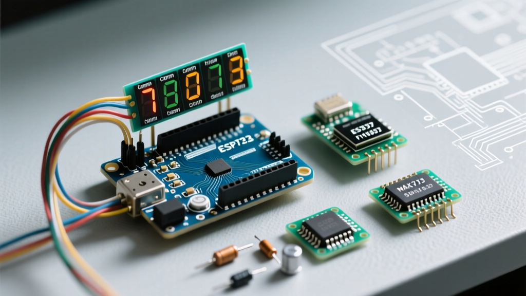
Whether you are building a digital clock, a temperature monitor, or a retro-style scoreboard, the Arduino 7 segment display remains one of the most reliable and visually striking output methods in a maker's arsenal. Unlike LCDs or OLEDs, 7-segment displays offer high-visibility, wide-angle readability that is perfect for industrial and DIY instrumentation.
At its core, a standard 7-segment display is simply an array of eight individual Light Emitting Diodes (LEDs). Seven of these LEDs are arranged in an 'H' or '8' pattern (labeled A through G), and the eighth is a decimal point (DP). By selectively illuminating specific segments, you can form numerals 0-9 and a limited subset of the alphabet.
Common Anode vs. Common Cathode: The Critical Distinction
Before wiring anything to your microcontroller, you must identify the internal topology of your display. This dictates whether your Arduino pins need to source or sink current. According to SparkFun's foundational LED tutorial, understanding current flow direction is the first step in preventing dead-on-arrival hardware.
| Feature | Common Cathode (CC) | Common Anode (CA) |
|---|---|---|
| Internal Wiring | All LED cathodes tied to GND | All LED anodes tied to VCC |
| Logic to Turn ON | Segment pin goes HIGH (5V) | Segment pin goes LOW (0V) |
| Logic to Turn OFF | Segment pin goes LOW (0V) | Segment pin goes HIGH (5V) |
| Arduino Compatibility | Easier for direct drive (source current) | Preferred for multiplexing (sink current) |
The I/O Pin Problem: Why Direct Wiring Fails
A single-digit display requires 8 digital I/O pins (plus a ground or VCC connection). If you are using a standard Arduino Uno (ATmega328P), you have 14 digital I/O pins. You could theoretically wire one display directly, perhaps two if you sacrifice your hardware serial and I2C pins. However, a standard 4-digit display module contains 32 individual LEDs. Direct wiring is mathematically and practically impossible on standard development boards.
Furthermore, the ATmega328P has strict current limitations. While the absolute maximum DC current per I/O pin is 40mA, the recommended operating condition is 20mA. More importantly, the total current through the VCC and GND pins must not exceed 200mA. Directly driving multiple bright LEDs will brownout your microcontroller or permanently damage the silicon.
The Solution: Dedicated Driver ICs (MAX7219 vs TM1637)
To solve the I/O and current limitations, the maker community relies on dedicated multiplexing driver ICs. In 2026, two architectures dominate the Arduino 7 segment ecosystem: the SPI-based MAX7219 and the proprietary 2-wire TM1637.
| Specification | MAX7219 (e.g., FC-1130BS Module) | TM1637 (e.g., 4-Bit Clock Module) |
|---|---|---|
| Communication Protocol | Standard Hardware SPI (MOSI, SCK, SS) | Proprietary 2-Wire (CLK, DIO) |
| Max Digits Supported | Up to 8 digits per chip (daisy-chainable) | Up to 6 digits per chip |
| Current Control | Hardware resistor ($R_{set}$) + internal PWM | Software-based 8-level brightness |
| Library Requirement | LedControl or MD_MAX72XX | TM1637Display |
| Typical Module Cost | $3.50 - $5.00 USD | $1.50 - $2.50 USD |
| Best Use Case | Complex dashboards, daisy-chained arrays | Simple clocks, basic sensor readouts |
Hardware Wiring: MAX7219 to Arduino Uno
The Analog Devices MAX7219 is a true workhorse. It handles all the multiplexing timing internally, freeing your Arduino to perform other tasks without interrupt-driven flickering. Here is the exact wiring sequence for a standard FC-1130BS 4-digit module using the hardware SPI bus.
- VCC: Connect to Arduino 5V. (Do not use 3.3V; the MAX7219 requires 5V logic and power).
- GND: Connect to Arduino GND.
- DIN (Data In): Connect to Arduino Pin 11 (MOSI on Uno/Nano).
- CS (Chip Select / LOAD): Connect to Arduino Pin 10 (SS).
- CLK (Clock): Connect to Arduino Pin 13 (SCK).
CRITICAL WARNING: The $R_{set}$ Resistor
Never power a bare MAX7219 chip without the external $R_{set}$ resistor (usually Pin 18 to VCC). This single resistor dictates the current supplied to ALL segments. A standard 10kΩ resistor yields roughly 40mA per segment peak (which averages to ~10mA per segment during multiplexing). Omitting this resistor will instantly destroy the IC and potentially your display.
C++ Implementation: Driving the Display
To interface with the MAX7219, we utilize the highly optimized LedControl library. Below is a production-ready sketch that initializes the display, clears it, and cycles through a 4-digit counter. This code leverages the Arduino SPI communication standards to ensure rapid data transfer.
#include "LedControl.h"

// Pin definitions for Arduino Uno
const int DIN_PIN = 11;
const int CLK_PIN = 13;
const int CS_PIN = 10;

// Initialize LedControl: DIN, CLK, CS, Number of Devices
LedControl lc = LedControl(DIN_PIN, CLK_PIN, CS_PIN, 1);

void setup() {
  // Wake up the MAX7219 from power-saving mode
  lc.shutdown(0, false);

  // Set brightness level (0 to 15)
  lc.setIntensity(0, 8);

  // Clear the display on boot
  lc.clearDisplay(0);
}

void loop() {
  for (int i = 0; i < 10000; i++) {
    printNumber(i);
    delay(50);
  }
}

void printNumber(int num) {
  int ones = num % 10;
  int tens = (num / 10) % 10;
  int hundreds = (num / 100) % 10;
  int thousands = (num / 1000) % 10;

  // Print to digits 3, 2, 1, 0 (Left to Right on most modules)
  lc.setDigit(0, 3, thousands, false);
  lc.setDigit(0, 2, hundreds, false);
  lc.setDigit(0, 1, tens, false);
  lc.setDigit(0, 0, ones, false);
}
Real-World Troubleshooting and Edge Cases
Even with proper wiring, physical hardware introduces variables that pure code cannot predict. Here are the most common failure modes encountered when working with Arduino 7 segment setups and how to resolve them.
1. Ghosting and Faint Segments
Symptom: When displaying the number '1', segments A and F light up brightly, but segments B and C glow faintly.
Cause: This is a classic multiplexing timing issue or a missing pull-down resistor on the base of the driving transistors (if using a custom-built discrete multiplex circuit). If using a MAX7219, ghosting almost always indicates a failing IC or a poorly soldered $R_{set}$ resistor allowing current leakage.
2. Severe Flickering Under Load
Symptom: The display flickers noticeably when the Arduino is executing heavy computational tasks or reading slow I2C sensors.
Cause: If you are manually multiplexing displays using delay() or software timers, blocking code will halt the multiplexing refresh rate. The human eye requires a refresh rate of at least 60Hz to perceive a steady image. Fix: Always use hardware driver ICs like the MAX7219, which maintain their own internal refresh oscillators independent of the Arduino's main loop.
3. Brownouts and Microcontroller Resets
Symptom: The Arduino resets randomly when multiple segments (like the number '8') are illuminated.
Cause: Power supply inadequacy. A 4-digit display showing '8888' illuminates 32 LEDs simultaneously (averaged via multiplexing). If your 5V regulator cannot supply the required current, the voltage drops below the ATmega328P's brownout detection threshold (typically 4.3V). Fix: Power the display module via a separate 5V buck converter capable of delivering at least 1A, ensuring the GND is shared with the Arduino.
Summary
Mastering the Arduino 7 segment display requires moving beyond simple digital writes and embracing dedicated multiplexing hardware. By understanding the electrical differences between common anode and cathode topologies, respecting the current limits of your microcontroller, and leveraging robust SPI drivers like the MAX7219, you can build instrumentation that is both visually striking and electrically sound.