
Why Most Traffic Light in Arduino Tutorials Fail
If you have ever searched for a traffic light in Arduino tutorial, you have likely encountered the classic three-LED blink sketch. While it serves as a basic introduction to digitalWrite(), almost every beginner tutorial relies heavily on the delay() function. In real-world embedded systems, delay() is a blocking function. It halts the microcontroller's CPU, meaning the system becomes entirely blind to external inputs—like a pedestrian pressing a crosswalk button—until the delay timer expires.
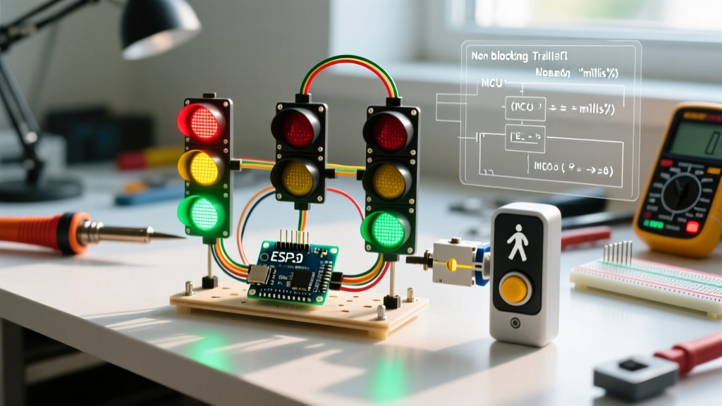
To build a truly responsive, intersection-grade smart traffic light, we must abandon blocking code. In this comprehensive 2026 guide, we will design a non-blocking Finite State Machine (FSM) powered by millis(), implement professional hardware debouncing to eliminate button bounce, and integrate a pedestrian crossing request system that safely interrupts the main road cycle without causing erratic light flashing.
The Problem with Software Debouncing
Mechanical tactile switches suffer from contact bounce. When pressed, the metal contacts physically vibrate, registering as dozens of rapid HIGH/LOW transitions over 1 to 5 milliseconds. Most tutorials suggest a software fix: adding delay(50) after reading the button. As established, this blocks the CPU. If a pedestrian presses the button while the main light is yellow, a 50ms software delay could push the transition logic out of sync, causing dangerous timing overlaps.
The professional solution is hardware debouncing using an RC low-pass filter. By combining a resistor and a capacitor, we smooth out the voltage spikes physically before the signal ever reaches the ATmega328P microcontroller's digital pin.
Calculating the RC Time Constant
We will use an external 10kΩ pull-up resistor and a 100nF (0.1µF) ceramic capacitor. The time constant (τ) is calculated as:
τ = R × C
τ = 10,000Ω × 0.0000001F = 0.001 seconds (1ms)
When the button is released, the capacitor charges through the 10kΩ resistor. It takes roughly 3τ (3ms) for the voltage to reach a stable HIGH threshold (above 3V for the ATmega328P). This perfectly filters out the 1-5ms mechanical bounce while remaining fast enough for human interaction. For a deeper dive into the physics of switch bounce, refer to this excellent breakdown by All About Circuits on switch bounce.
2026 Hardware Bill of Materials (BOM)
Building this project is highly cost-effective. Below is the precise component list with estimated 2026 market pricing for hobbyist quantities.
| Component | Specification | Qty | Est. Cost (USD) |
|---|---|---|---|
| Microcontroller | Arduino Nano (ATmega328P) | 1 | $4.50 |
| LEDs (Main) | 5mm Diffused (Red, Yellow, Green) | 3 | $0.30 |
| LEDs (Pedestrian) | 5mm Diffused (Red, Green) | 2 | $0.20 |
| Current Limiting Resistors | 220Ω (1/4W) | 5 | $0.10 |
| Pull-Up Resistor | 10kΩ (1/4W) | 1 | $0.05 |
| Debounce Capacitor | 100nF (0.1µF) Ceramic | 1 | $0.05 |
| Tactile Switch | 6x6mm Momentary | 1 | $0.10 |
Wiring Matrix and Pinout
Proper wiring is critical for the FSM to read inputs accurately and drive the LEDs without exceeding the ATmega328P's 40mA absolute maximum pin current limit (we will draw roughly 15mA per LED).
| Arduino Pin | Connection Target | Notes |
|---|---|---|
| D2 | Pedestrian Button | Connect 10kΩ to 5V, 100nF to GND. Button connects D2 to GND. |
| D8 | Main Road Red LED | Connect via 220Ω resistor to GND. |
| D9 | Main Road Yellow LED | Connect via 220Ω resistor to GND. |
| D10 | Main Road Green LED | Connect via 220Ω resistor to GND. |
| D11 | Pedestrian Red LED | Connect via 220Ω resistor to GND. |
| D12 | Pedestrian Green LED | Connect via 220Ω resistor to GND. |
Designing the Finite State Machine (FSM)
A robust traffic light in Arduino requires distinct operational states. Instead of writing sequential if/else spaghetti, we define an enum to track the exact phase of the intersection.
- STATE_MAIN_GREEN: Main road flows. Pedestrian red is solid. System listens for button presses.
- STATE_MAIN_YELLOW: Main road cautions. Triggered only after the pedestrian button is pressed and the minimum green time has elapsed.
- STATE_PED_WALK: Main road is red. Pedestrian green is solid. Timed for safe crossing.
- STATE_PED_FLASH: Main road remains red. Pedestrian green flashes to warn of impending light change.
By tracking previousMillis, we can execute state transitions based on elapsed time without pausing the main loop. This ensures the microcontroller can continuously poll the pedestrian button and handle serial debugging simultaneously. For more on non-blocking timing, consult the official Arduino millis() reference documentation.
The Non-Blocking C++ Code
Upload the following sketch to your Arduino Nano. Note the use of hardware debouncing logic combined with the millis() state machine.
// Pin Definitions
const int BTN_PED = 2;
const int MAIN_RED = 8;
const int MAIN_YELLOW = 9;
const int MAIN_GREEN = 10;
const int PED_RED = 11;
const int PED_GREEN = 12;

// State Machine Enum
enum TrafficState {
  STATE_MAIN_GREEN,
  STATE_MAIN_YELLOW,
  STATE_PED_WALK,
  STATE_PED_FLASH
};

TrafficState currentState = STATE_MAIN_GREEN;
unsigned long stateStartTime = 0;
bool pedestrianRequested = false;

// Timing Constants (in milliseconds)
const unsigned long MIN_GREEN_TIME = 10000; // 10s minimum main green
const unsigned long YELLOW_TIME = 3000;     // 3s yellow caution
const unsigned long PED_WALK_TIME = 8000;   // 8s solid walk
const unsigned long PED_FLASH_TIME = 4000;  // 4s flashing warning
const unsigned long FLASH_INTERVAL = 500;   // 0.5s flash rate

void setup() {
  pinMode(BTN_PED, INPUT); // Using external 10k pull-up
  pinMode(MAIN_RED, OUTPUT);
  pinMode(MAIN_YELLOW, OUTPUT);
  pinMode(MAIN_GREEN, OUTPUT);
  pinMode(PED_RED, OUTPUT);
  pinMode(PED_GREEN, OUTPUT);

  Serial.begin(9600);
  stateStartTime = millis();
}

void loop() {
  unsigned long currentMillis = millis();

  // Hardware debounced button read (Active LOW due to pull-up)
  if (digitalRead(BTN_PED) == LOW && currentState == STATE_MAIN_GREEN) {
    pedestrianRequested = true;
  }

  switch (currentState) {
    case STATE_MAIN_GREEN:
      setLights(HIGH, LOW, LOW, HIGH, LOW);
      if (pedestrianRequested && (currentMillis - stateStartTime >= MIN_GREEN_TIME)) {
        transitionTo(STATE_MAIN_YELLOW, currentMillis);
      }
      break;

    case STATE_MAIN_YELLOW:
      setLights(LOW, HIGH, LOW, HIGH, LOW);
      if (currentMillis - stateStartTime >= YELLOW_TIME) {
        transitionTo(STATE_PED_WALK, currentMillis);
      }
      break;

    case STATE_PED_WALK:
      setLights(HIGH, LOW, LOW, LOW, HIGH);
      if (currentMillis - stateStartTime >= PED_WALK_TIME) {
        transitionTo(STATE_PED_FLASH, currentMillis);
      }
      break;

    case STATE_PED_FLASH:
      bool flashState = ((currentMillis / FLASH_INTERVAL) % 2) == 0;
      setLights(HIGH, LOW, LOW, LOW, flashState);
      if (currentMillis - stateStartTime >= PED_FLASH_TIME) {
        pedestrianRequested = false;
        transitionTo(STATE_MAIN_GREEN, currentMillis);
      }
      break;
  }
}

void setLights(bool mRed, bool mYel, bool mGrn, bool pRed, bool pGrn) {
  digitalWrite(MAIN_RED, mRed);
  digitalWrite(MAIN_YELLOW, mYel);
  digitalWrite(MAIN_GREEN, mGrn);
  digitalWrite(PED_RED, pRed);
  digitalWrite(PED_GREEN, pGrn);
}

void transitionTo(TrafficState newState, unsigned long currentMillis) {
  currentState = newState;
  stateStartTime = currentMillis;
}
Edge Cases and Troubleshooting
Even with a robust design, physical hardware introduces variables that simulation environments hide. Here are the most common failure modes when building this traffic light in Arduino and how to resolve them:
1. Phantom Button Presses (Floating Pins)
Symptom: The pedestrian light triggers randomly without pressing the button.
Cause: The digital pin is acting as an antenna, picking up electromagnetic interference (EMI) from nearby AC mains wiring or breadboard parasitic capacitance.
Fix: Verify your 10kΩ pull-up resistor is securely connected to the 5V rail. If you omitted the external resistor, change pinMode(BTN_PED, INPUT); to pinMode(BTN_PED, INPUT_PULLUP); in the code to engage the ATmega328P's internal 20kΩ-50kΩ pull-up resistors.
2. LED Flickering During State Transitions
Symptom: LEDs briefly dim or flash erratically when switching from STATE_PED_FLASH to STATE_MAIN_GREEN.
Cause: Power supply voltage droop. Driving 4 LEDs simultaneously (Main Red + Ped Green during flash) pulls roughly 60mA. If powered via a cheap USB hub, the voltage may dip below 4.5V, causing the microcontroller to brownout momentarily.
Fix: Power the Arduino Nano via the VIN pin with a regulated 7V-9V DC power supply, or ensure your USB source can deliver a stable 500mA+.
3. Timing Drift Over Long Uptimes
Symptom: After 49 days of continuous operation, the traffic light freezes or behaves erratically.
Cause: The millis() function returns an unsigned long, which maxes out at 4,294,967,295 milliseconds (approx. 49.7 days) before rolling over to zero.
Fix: The code provided above inherently handles rollover safely by using subtraction (currentMillis - stateStartTime) rather than addition. Never write if (currentMillis > stateStartTime + INTERVAL), as this will break during a rollover event. Always use the subtraction method demonstrated in the FSM.
Conclusion
Building a reliable traffic light in Arduino requires moving beyond basic delay loops and embracing event-driven architecture. By implementing a hardware RC debounce filter and a non-blocking Finite State Machine, you ensure your intersection remains responsive, safe, and immune to the timing drifts that plague beginner sketches. Whether you are prototyping a smart city model or learning embedded C++ best practices, this architecture forms the foundation for all complex, multi-input MCU systems.