
Demystifying the ISP Programmer for Arduino
When most makers begin their microcontroller journey, they rely exclusively on the Arduino IDE's standard 'Upload' button. This process utilizes a pre-installed UART or USB bootloader to receive compiled code. However, as projects evolve into custom PCB designs, low-power ATtiny builds, or production-level firmware deployments, the standard bootloader becomes a bottleneck. This is where an ISP programmer for Arduino transitions from an optional accessory to an essential laboratory tool.
ISP stands for In-System Programming. It allows you to program the microcontroller directly via the Serial Peripheral Interface (SPI) bus, completely bypassing the bootloader. This guide explores the underlying SPI mechanics, compares modern ISP hardware available in 2026, and provides actionable frameworks for managing fuse bits and recovering bricked chips.
The Anatomy of In-System Programming (SPI)
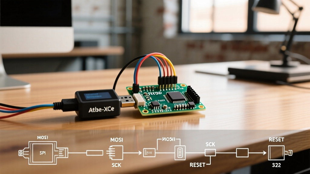
Unlike asynchronous serial communication (UART), which relies on agreed-upon baud rates, ISP utilizes the synchronous SPI protocol. The programmer acts as the SPI Master, while the target AVR microcontroller acts as the SPI Slave. Programming occurs over four primary logic lines, plus power and ground:
- MOSI (Master Out Slave In): Carries data and instructions from the programmer to the MCU.
- MISO (Master In Slave Out): Returns verification data and memory reads from the MCU to the programmer.
- SCK (Serial Clock): Synchronizes the data transfer.
- RESET: Held LOW to keep the MCU in programming mode, preventing it from executing user code.
The Golden Rule of ISP Clock Speeds
A frequent point of failure for beginners is the SCK frequency. According to the official Microchip ATmega328P datasheet, the ISP clock frequency (SCK) must strictly adhere to the target CPU's clock speed. If the target MCU is running below 12 MHz, the SCK frequency must be less than 1/4 of the target CPU frequency. If the CPU is running at 12 MHz or higher, SCK must be less than 1/6 of the CPU frequency. Attempting to ISP-program a fresh ATmega328P (which defaults to the 1 MHz internal oscillator) with a programmer hardcoded to 1 MHz SCK will result in an avrdude: initialization failed, rc=-1 error.
ISP Hardware Comparison Matrix (2026)
Selecting the right ISP programmer for Arduino depends on your target voltage, budget, and whether you need advanced debugging capabilities. Below is a comparison of the most reliable hardware options currently on the market.
| Programmer Model | Protocol / Interface | Target Voltage Support | Avg. Price (2026) | Best Use Case |
|---|---|---|---|---|
| Generic USBasp (Clone) | USB 2.0 / SPI | 5V only (3.3V via mod) | $5 - $9 | Hobbyist bootloader burning, 5V ATmega328P |
| Pololu USB AVR Programmer v2.1 | USB / SPI | 1.8V to 5.5V (Auto-sensing) | $23.95 | Custom PCBs, mixed-voltage logic, ATtiny85 |
| Microchip Atmel-ICE (MCP500) | USB / SPI, debugWIRE, JTAG | 1.62V to 5.5V | $135.00 | Professional firmware dev, on-chip debugging |
| Arduino as ISP (DIY) | UART to SPI bridge | Depends on host Arduino | $0 (if owned) | Emergency unbricking, educational purposes |
Expert Insight: While the $6 generic USBasp is ubiquitous, it lacks 3.3V logic level shifting out of the box. If you are programming a 3.3V ATmega328P or an ATtiny85 running on a lithium-ion battery circuit, the Pololu v2.1 is vastly superior due to its auto-sensing VCC target tracking, preventing catastrophic overvoltage damage to your MCU's GPIO pins.
Core Use Cases: Why Bypass the Bootloader?
1. Reclaiming Flash Memory and Instant Execution
The standard Arduino Uno (ATmega328P) bootloader occupies 1.5 KB to 2 KB of flash memory. Furthermore, upon every power cycle, the bootloader introduces a ~1-second delay while it waits for incoming serial data. By using an ISP programmer to upload your .hex file directly to the application section, you reclaim that flash space and achieve instant execution upon power-up—critical for battery-powered sensor nodes and timing-sensitive interrupts.
2. Programming UART-Less Microcontrollers
The ATtiny85 and ATtiny13 families do not possess a hardware UART peripheral. While software serial implementations exist, they are unreliable for bootloading. An ISP programmer is the only native, robust method to flash code to these diminutive 8-pin DIP microcontrollers.
3. Recovering 'Bricked' AVRs
If you accidentally upload a sketch that immediately disables the serial interface, or if a power brown-out corrupts the bootloader section of the flash memory, the Arduino IDE will throw a stk500_getsync() attempt 10 of 10 error. An ISP programmer bypasses the corrupted bootloader entirely, communicating directly with the silicon to flash a fresh bootloader or overwrite the bad sketch.
The Danger Zone: AVR Fuse Bits Explained
Fuse bits are non-volatile configuration bytes that dictate the fundamental hardware behavior of the AVR chip. They are not erased when you upload new code via ISP; they must be explicitly written. There are three fuse bytes: Low, High, and Extended.
Managing fuses manually is risky. A single incorrect bit flip can soft-brick your microcontroller. We highly recommend using the Engbedded AVR Fuse Calculator to generate the exact hexadecimal values and avrdude commands before executing them.
CRITICAL WARNING: Never enable the RSTDISBL (Reset Disable) fuse on an ATmega328P unless you have a dedicated High-Voltage Parallel Programmer (HVPP) on hand. Enabling this fuse converts the RESET pin into a standard I/O pin, permanently disabling ISP communication. Standard ISP programmers cannot recover a chip with RSTDISBL enabled.
Common Fuse Configurations
- Arduino Uno (16MHz External Crystal): Low:
0xFF, High:0xDE, Extended:0xFD. (Includes 2KB bootloader). - Standalone ATmega328P (8MHz Internal Oscillator, No Bootloader): Low:
0xE2, High:0xD9, Extended:0xFF. (Ideal for low-power coin-cell projects).
Wiring the 6-Pin ICSP Header
The industry standard for ISP programming is the 6-pin ICSP header (2x3 grid, 0.1-inch pitch). When looking at the official Arduino ISP documentation and standard AVR development boards, Pin 1 is typically denoted by a small triangle or dot on the silkscreen.
Here is the standard pinout mapping to the ATmega328P-PU (28-pin DIP):
- MISO: DIP Pin 18 (PB4)
- VCC: DIP Pin 7 or 20 (Connect to 5V or 3.3V depending on your target)
- SCK: DIP Pin 19 (PB5)
- MOSI: DIP Pin 17 (PB3)
- RESET: DIP Pin 1 (PC6)
- GND: DIP Pin 8 or 22
Pro-Tip for 'Arduino as ISP': If you are using an Arduino Uno as a makeshift ISP programmer, you must place a 10µF electrolytic capacitor between the RESET and GND pins of the host Uno (cathode to GND). This prevents the host Uno's auto-reset circuit from triggering when the IDE opens the serial port to initiate the programming sequence.
Advanced Workflow: Avrdude CLI Integration
While the Arduino IDE supports ISP via the 'Upload Using Programmer' option, professional embedded engineers rely on the avrdude Command Line Interface for automated build pipelines and precise memory manipulation.
To read the current flash memory of an ATmega328P using a Pololu programmer and save it to a backup file, use the following terminal command:
avrdude -c stk500v2 -P /dev/ttyACM0 -p m328p -U flash:r:backup_firmware.hex:iTo wipe the chip, set the fuses for an 8MHz internal clock, and upload a raw hex file in a single chain:
avrdude -c stk500v2 -P /dev/ttyACM0 -p m328p -e -U lfuse:w:0xE2:m -U hfuse:w:0xD9:m -U flash:w:main.hex:iTroubleshooting Common ISP Failures
Even with correct wiring, ISP programming can fail. Here is a diagnostic framework for the most common avrdude errors:
rc=-1ortarget doesn't answer: Check your SCK speed. If the target is running on a slow internal oscillator (1 MHz), force the programmer into slow-clock mode. In the Arduino IDE, this is sometimes handled automatically, but via CLI, you may need to append the-B 125kHzflag to slow down the bit-clock.invalid signature: The programmer is reading garbage data on the MISO line. This usually indicates a missing common ground between the programmer and the target circuit, or a loose jumper wire on the SPI bus.- Verification Errors: If the code uploads but fails verification, your target VCC might be sagging under the load of the programming sequence. Ensure your power supply can source at least 100mA, and add a 100nF decoupling capacitor directly across the VCC and GND pins of the target MCU.
Summary
Mastering the ISP programmer for Arduino unlocks the true potential of the AVR architecture. By stepping outside the constraints of the UART bootloader, you gain absolute control over the silicon's memory, clock configurations, and power states. Whether you are recovering a corrupted ATmega328P, deploying a fleet of ATtiny85 sensors, or optimizing flash memory for a complex robotics sketch, understanding SPI protocols and fuse bit management is a mandatory milestone in your embedded systems education.