
The Electromagnetic Anatomy of a Stepper Motor
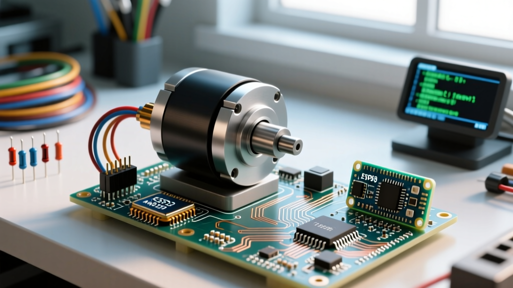
When you wire an Arduino step motor setup for a CNC router, 3D printer, or robotic arm, you are not simply turning a shaft on and off like a standard DC motor. You are orchestrating a precise sequence of electromagnetic phase energizations. The most common motor in the maker space is the NEMA 17 (specifically the 42x42mm faceplate standard), with the 17HS4401 being the ubiquitous workhorse rated for 1.5A per phase and roughly 40 N·cm (56 oz·in) of holding torque.
Inside a standard 1.8° bipolar stepper motor, you will find a rotor with 50 interlocking teeth and a stator featuring four distinct electromagnetic phases. By energizing these phases in a specific sequence (A-B-A'-B'), the magnetic field pulls the rotor teeth into alignment, resulting in exactly 200 full steps per revolution. Understanding this physical reality is critical because it dictates everything from your driver selection to your firmware acceleration profiles.
Why Your Arduino Step Motor Loses Torque at High Speeds
A frequent point of frustration for beginners is discovering that a stepper motor that can effortlessly push a 3D printer gantry at 50 RPM suddenly stalls and vibrates violently at 400 RPM. This is not a defect; it is a fundamental law of physics governed by coil inductance and back-electromotive force (Back-EMF).
As the motor spins faster, the time window to push current through the highly inductive stator coils shrinks. Furthermore, the spinning permanent magnet rotor generates a reverse voltage (Back-EMF) that actively fights your driver's supply voltage. According to Texas Instruments stepper driver architecture documentation, the rate at which current can rise in the coil is directly proportional to the supply voltage. This is exactly why upgrading a CNC machine from a 12V power supply to a 24V or 36V power supply dramatically improves high-speed torque and prevents missed steps during rapid traversals.
Driver Selection Matrix: A4988 vs. DRV8825 vs. TMC2209
The Arduino microcontroller (whether an 8-bit Uno or a 32-bit Zero/ESP32) cannot source the 1.5A+ required by the motor coils directly. You must use a dedicated chopper driver. These drivers use Pulse Width Modulation (PWM) to regulate current and generate microsteps. Here is how the three dominant market options compare in 2026:
| Driver IC | Max Current (RMS) | Max Microstepping | Acoustic Noise | Avg. Clone Price (2026) |
|---|---|---|---|---|
| Allegro A4988 | 1.0A (w/o cooling) | 1/16 | High (Whine) | $1.50 - $2.50 |
| TI DRV8825 | 1.5A (w/o cooling) | 1/32 | Medium | $2.00 - $3.50 |
| Trinamic TMC2209 | 2.0A (w/ cooling) | 1/256 (Interpolated) | Silent (StealthChop) | $8.00 - $12.00 |
For basic prototyping, the A4988 is sufficient. However, for any precision or noise-sensitive application, the TMC2209 is the undisputed standard. As detailed in the Analog Devices TMC2209 datasheet, its StealthChop2 technology eliminates the PWM switching noise that plagues older drivers, while its UART interface allows dynamic current tuning directly from your Arduino code.
The Vref Calibration Ritual (Do Not Skip This)
The most common cause of dead stepper drivers and melted breadboard wires is failing to set the current limit (Vref) before connecting the motor. If you ship 2A into a 1A rated coil, you will demagnetize the rotor and destroy the driver silicon.
To calibrate an A4988 or DRV8825, you need a digital multimeter and a small ceramic screwdriver. The standard formula for a Pololu-style carrier board with 0.05Ω sense resistors is:
Vref = Current Limit / 2.5
Example: For a 1.5A motor, Vref = 1.5 / 2.5 = 0.6V
For exact wiring and resistor variations, always consult the manufacturer's specific documentation, such as Pololu's A4988 Stepper Motor Driver Carrier page, as clone boards from overseas marketplaces frequently swap the 0.05Ω sense resistors for 0.1Ω resistors, which halves the required Vref voltage.
Step-by-Step Vref Measurement:
- Power the driver's logic side (VDD) with 5V from the Arduino, and the motor side (VMOT) with your main power supply (e.g., 12V).
- Set your multimeter to DC Voltage (20V range).
- Place the black probe on the driver's GND pin and the red probe gently on the metal trim-pot screw.
- Turn the potentiometer counter-clockwise to lower the voltage, or clockwise to raise it, until you hit your target Vref.
Microstepping: Resolution vs. Reality
Microstepping works by proportionally varying the current between two adjacent phases, creating intermediate magnetic equilibrium points. Setting a driver to 1/16 microstepping divides the 1.8° full step into 0.1125° increments, yielding 3,200 steps per revolution.
However, microstepping does not equal accuracy. Due to magnetic hysteresis, friction, and detent torque, a 1/16 microstep might only yield 1/4 of the expected physical movement under load. The true benefit of microstepping is not infinite positional accuracy, but rather the reduction of low-speed resonance and the smoothing of torque delivery. If you need true sub-micron accuracy, you must pair a full-step or half-step configuration with a closed-loop encoder, rather than relying on open-loop 1/32 microstepping.
Overcoming Mid-Band Resonance
Bipolar steppers suffer from a phenomenon known as mid-band resonance, typically occurring between 100 and 300 RPM. At these speeds, the frequency of the stepping pulses aligns with the natural mechanical harmonic frequency of the rotor and load, causing the motor to violently oscillate, lose synchronization, and stall.
- Mechanical Fix: Attach a silicone-mass mechanical damper to the rear shaft of the NEMA 17. This absorbs the harmonic kinetic energy.
- Electrical Fix: Use a driver with active resonance dampening (like the TMC2209's SpreadCycle mode) which dynamically alters the PWM decay pattern to disrupt the harmonic buildup.
- Firmware Fix: Program your Arduino to accelerate rapidly through the 100-300 RPM danger zone using an S-curve (jerk-limited) acceleration profile.
Acceleration Profiling in Firmware
A stepper motor has high inertia. If your Arduino sketch commands an immediate jump from 0 to 1000 RPM using a simple delayMicroseconds() loop, the rotor will simply vibrate in place while the magnetic field spins ahead of it. You must use acceleration profiling.
The industry-standard AccelStepper library handles the complex trapezoidal velocity math. When configuring your sketch, the setMaxSpeed() and setAcceleration() functions are critical. For a standard 1.5A NEMA 17 driving a leadscrew, a safe starting acceleration is 1000 to 2000 steps/sec^2. Pushing this value to 8000 steps/sec^2 without reducing the microstep divider will almost certainly result in stalled steps at the beginning of the movement.
By mastering the interplay between supply voltage, driver decay modes, and firmware acceleration curves, your Arduino step motor projects will transition from jittery prototypes to industrial-grade motion systems.