
Mastering the LCD1602 Arduino Display via I2C
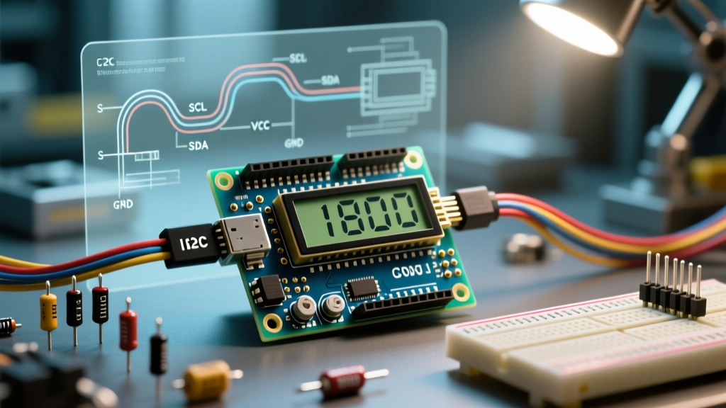
The LCD1602 is arguably the most ubiquitous character display in the maker ecosystem. Featuring a 16-column by 2-row liquid crystal matrix, it is driven by the legendary Hitachi HD44780 controller. While parallel wiring was the standard a decade ago, modern lcd1602 arduino projects almost exclusively use an I2C backpack adapter. This reduces the required microcontroller pins from six down to just two (SDA and SCL), freeing up vital GPIO for sensors and actuators.
In this comprehensive 2026 guide, we will cover the exact hardware requirements, I2C address discovery, advanced Character Generator RAM (CGRAM) manipulation, and the real-world hardware edge cases that cause 90% of beginner failures.
Hardware BOM and 2026 Pricing
Before writing code, ensure you have the correct hardware. Generic clone modules are incredibly cheap, but understanding the silicon on the backpack is critical for troubleshooting.
| Component | Specification / Model | Estimated Price (2026) |
|---|---|---|
| Microcontroller | Arduino Uno R4 Minima or Nano ESP32 | $18.00 - $27.00 |
| Display Module | LCD1602 (Blue or Green backlight) + PCF8574 I2C Backpack | $2.50 - $4.50 |
| Wiring | F-to-F Jumper Wires (20cm) | $3.00 (pack) |
| Pull-up Resistors | 4.7kΩ (Only required for 3.3V logic boards like ESP32) | $0.10 |
Step-by-Step Wiring Guide
The I2C backpack translates serial I2C commands into the parallel signals the HD44780 requires. However, logic levels matter. The standard LCD1602 requires 5V logic for reliable operation and backlight illumination. If you are using a 5V board like the Uno R4, wiring is direct. If you are using a 3.3V board like the Nano ESP32 or Raspberry Pi Pico, you must use a logic level shifter or add external 4.7kΩ pull-up resistors to 5V on the SDA and SCL lines to ensure the I2C bus registers the high states correctly.
Pinout Matrix
| I2C Backpack Pin | Arduino Uno R4 (5V) | Nano ESP32 (3.3V Logic) | Function |
|---|---|---|---|
| GND | GND | GND | Common Ground |
| VCC | 5V | 5V (VIN or 5V pin) | Power & Backlight |
| SDA | A4 | GPIO 21 (with 4.7k pull-up) | Serial Data |
| SCL | A5 | GPIO 22 (with 4.7k pull-up) | Serial Clock |
Step 1: I2C Address Discovery
The most common point of failure in an lcd1602 arduino setup is using the wrong I2C address in the code. The I2C backpack utilizes a Texas Instruments or NXP PCF8574 I/O expander chip. There are two common variants on the market:
- PCF8574T: Default I2C address is
0x27(Hexadecimal). - PCF8574AT: Default I2C address is
0x3F(Hexadecimal).
Before writing your main sketch, upload an I2C Scanner script (available via the Arduino IDE Examples menu under Wire > I2CScanner) to verify the exact address. The Arduino Wire library handles the low-level bus scanning seamlessly.
Step 2: Library Setup and Core Code
Install the LiquidCrystal_I2C library by Frank de Brabander via the Arduino Library Manager. Below is a production-ready boilerplate sketch that initializes the display, handles the backlight, and prints dynamic sensor data.
#include <Wire.h>
#include <LiquidCrystal_I2C.h>

// Initialize with address 0x27, 16 columns, 2 rows
LiquidCrystal_I2C lcd(0x27, 16, 2);

void setup() {
  lcd.init();
  lcd.backlight();

  lcd.setCursor(0, 0);
  lcd.print("ElectricalFlux");
  lcd.setCursor(0, 1);
  lcd.print("Booting up...");
  delay(2000);
  lcd.clear();
}

void loop() {
  // Simulate reading a sensor
  float voltage = analogRead(A0) * (5.0 / 1023.0);

  lcd.setCursor(0, 0);
  lcd.print("Voltage: ");
  lcd.print(voltage, 2);
  lcd.print(" V");

  delay(500);
}
Advanced Technique: Custom Characters via CGRAM
The HD44780 controller contains 64 bytes of Character Generator RAM (CGRAM). This allows you to define up to eight custom 5x8 pixel characters. This is highly useful for creating battery indicators, custom arrows, or the degree symbol (°) for temperature sensors, which is not natively mapped in the standard ASCII ROM of cheap clone displays.
Defining a Custom Degree Symbol
byte degreeSymbol[8] = {
  B00110,
  B01001,
  B01001,
  B00110,
  B00000,
  B00000,
  B00000,
  B00000
};

void setup() {
  lcd.init();
  lcd.createChar(0, degreeSymbol); // Store in CGRAM slot 0
  lcd.backlight();
  lcd.setCursor(0,0);
  lcd.print("Temp: 24");
  lcd.write(0); // Print the custom character
  lcd.print("C");
}
Real-World Troubleshooting and Edge Cases
Even with perfect code, hardware quirks can cause the LCD1602 to malfunction. Use this diagnostic framework to resolve common issues:
The "Blank Screen" Contrast Issue
If the backlight is on but no text is visible (or you only see solid white rectangles on the top row), the contrast is misconfigured. Locate the blue trimpot (potentiometer) on the back of the I2C backpack. Using a #00 Phillips screwdriver, slowly turn the screw counter-clockwise until the characters become crisp against the background. This is a physical hardware adjustment, not a software one.
Backlight Not Turning On
Most I2C backpacks feature a small jumper cap situated near the VCC and GND pins on the top left of the PCB. This jumper bridges the power supply to the backlight LED transistor. If this jumper is removed, lcd.backlight() will execute in code, but the screen will remain dark. Ensure the jumper cap is securely seated.
Garbage Characters and Flickering
If the display prints random, unreadable Japanese or Cyrillic characters, or flickers intermittently, you are experiencing I2C bus noise or an address mismatch.
- Address Mismatch: You likely defined
0x27in code, but the board uses the PCF8574AT chip (0x3F). Re-run the I2C scanner. - Bus Noise: I2C is highly susceptible to electromagnetic interference (EMI) from nearby motors or relays. Keep I2C wires under 30cm in length. If longer runs are required, use twisted-pair cabling and lower the I2C clock speed using
Wire.setClock(10000);in your setup function. - Insufficient Current: The backlight LED draws roughly 20mA to 40mA. If powering the Arduino via a weak USB hub, the voltage may sag, causing the HD44780 to reset and output garbage. Power the Arduino via the barrel jack with a 7V-9V 1A power supply for stability.
Summary
Integrating an lcd1602 arduino display via I2C is a foundational skill for embedded systems prototyping. By understanding the underlying PCF8574 address mapping, respecting 5V logic requirements, and leveraging CGRAM for custom UI elements, you can build robust, professional-looking hardware interfaces without exhausting your microcontroller's GPIO pins.