
The Reality of GPS Integration in Maker Projects
Integrating a module gps arduino setup is a rite of passage for robotics and tracking projects. However, GPS receivers are notoriously unforgiving when it comes to power delivery, serial timing, and environmental line-of-sight. Whether you are using a budget u-blox NEO-6M clone or a high-end Beitian BN-220 dual-constellation receiver, the symptoms of failure usually fall into three categories: the dreaded "No-Fix" blinking LED, garbage characters on the Serial Monitor, or silent parsing failures in your code.
This diagnostic guide bypasses generic advice and dives deep into the electrical and protocol-level failure modes of GPS modules in 2026, providing exact troubleshooting steps to get your NMEA sentences flowing cleanly.
Module Hardware Matrix: Know Your Default States
Before troubleshooting, you must know the factory defaults of your specific silicon. A common error is assuming all GPS modules communicate at 9600 baud. Below is a comparison of the most common modules used in Arduino ecosystems today.
| Module Model | Default Baud Rate | Logic Level | Constellations | Avg Cost (2026) |
|---|---|---|---|---|
| u-blox NEO-6M | 9600 bps | 3.3V (Clones often 5V tolerant) | GPS (50-ch) | $4 - $8 |
| u-blox NEO-M8N | 9600 bps | 3.3V (Strict) | GPS/GLONASS/Galileo | $28 - $40 |
| Beitian BN-220 | 115200 bps | 3.3V (Strict) | GPS/GLONASS (Dual) | $12 - $18 |
| Quectel L80-R | 9600 bps | 3.3V | GPS/GLONASS | $15 - $22 |
Symptom 1: The Blinking Red LED (No-Fix State)
Most breakout boards feature a red LED tied to the PPS (Pulse Per Second) or FIX pin. If this LED is blinking rapidly or stays solidly lit without pulsing, the module has not achieved a 3D fix. According to the official u-blox NEO-6 series documentation, a cold start Time to First Fix (TTFF) typically takes 27 seconds under open sky, but can exceed 15 minutes if the almanac data is missing or the signal is obstructed.
Diagnostic Steps for No-Fix Errors
- Verify the Ceramic Patch Antenna: The square ceramic element must face the sky directly. It cannot be enclosed in a metal project box, and it cannot be placed indoors. Drywall and wood attenuate the 1.575 GHz L1 signal severely.
- Check for EEPROM Battery Failure: Genuine NEO-6M and M8N modules include a small MS621FE or ML1220 coin cell (or supercapacitor) to maintain the Real-Time Clock (RTC) and ephemeris data. If your module is a cheap clone, this battery is often dead on arrival, forcing a full cold start every time you power cycle the Arduino.
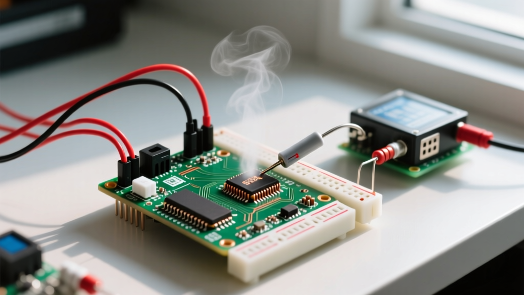
- Measure the 3.3V Rail Under Load: During satellite acquisition, a GPS module can spike to 45mA of current draw. If you are powering the module via the Arduino's onboard 3.3V regulator (which is often limited to 50mA and already powering the ATmega328P), the voltage will brownout, causing the module to continuously reset before achieving a fix. Fix: Use an external AMS1117-3.3 LDO regulator powered from the 5V pin.
Symptom 2: Garbage Characters on the Serial Monitor
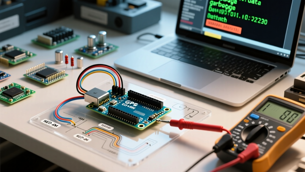
If your Serial Monitor displays a stream of `?`, `ÿ`, or random symbols, you are experiencing a baud rate mismatch or a buffer overflow. This is the most frequent issue when pairing a module gps arduino configuration using an Uno or Nano.
The SoftwareSerial Baud Rate Trap
The Arduino SoftwareSerial library relies on pin-change interrupts and software timing to emulate a UART port. While the library technically allows you to initialize a port at 115200 baud, the 16MHz ATmega328P cannot reliably process these interrupts while simultaneously executing your main loop and updating a display. Packets will drop, resulting in corrupted NMEA sentences and checksum failures.
Expert Rule of Thumb: Never use SoftwareSerial for GPS modules that default to 115200 baud (like the BN-220). Either reconfigure the GPS module's baud rate to 9600 using u-center software, or upgrade to an Arduino Mega (using hardware Serial1/Serial2) or an ESP32 (using HardwareSerial).
Wiring Verification: TX to RX, RX to TX
It sounds elementary, but serial cross-wiring remains a top culprit. The TX pin of the GPS module must connect to the RX pin of the Arduino (or the designated SoftwareSerial RX pin). Furthermore, ensure you are using a common ground. A floating ground between the GPS breakout and the MCU will cause erratic voltage logic thresholds, manifesting as intermittent garbage data.
Symptom 3: TinyGPS++ Returns Invalid or Blank Data
Your serial monitor shows clean NMEA sentences (e.g., $GPGGA,123519,4807.038,N,01131.000,E,1,08,0.9,545.4,M,46.9,M,,*47), but the TinyGPS++ library returns 0.00 for latitude and **** for altitude.
Root Causes for Parsing Failures
- Checksum Mismatches: NMEA sentences end with an asterisk and a two-character hexadecimal checksum. If your serial buffer overflows and drops a single byte, the checksum fails, and TinyGPS++ silently discards the sentence. Check your
gps.charsProcessed()andgps.failedChecksum()counters. If the failed checksum count is rising, you have a timing/buffer issue. - Starvation of the
encode()Function: TinyGPS++ requires you to feed it characters continuously. If your Arduino sketch includes blocking delays (e.g.,delay(1000)for a sensor read or an ultrasonic ping), the serial buffer (which is only 64 bytes deep on the ATmega328P) will overflow. GPS modules output roughly 300-500 characters per second; a one-second delay guarantees data loss. Fix: Replace all blocking delays withmillis()based non-blocking timers. - Missing GGA/RMC Sentences: Some ultra-low-power modules disable certain NMEA sentences to save bandwidth. TinyGPS++ relies heavily on GPGGA (for altitude and fix quality) and GPRMC (for date, speed, and course). Use the u-blox u-center software to ensure these specific NMEA strings are enabled in the module's configuration.
Advanced Troubleshooting: I2C vs. UART Conflicts
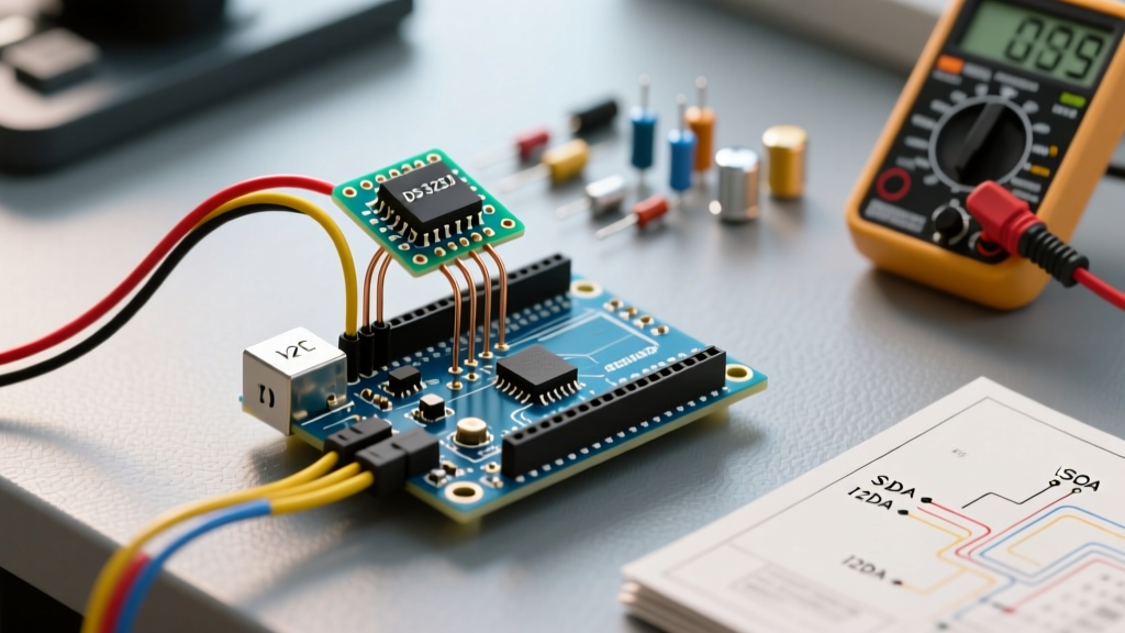
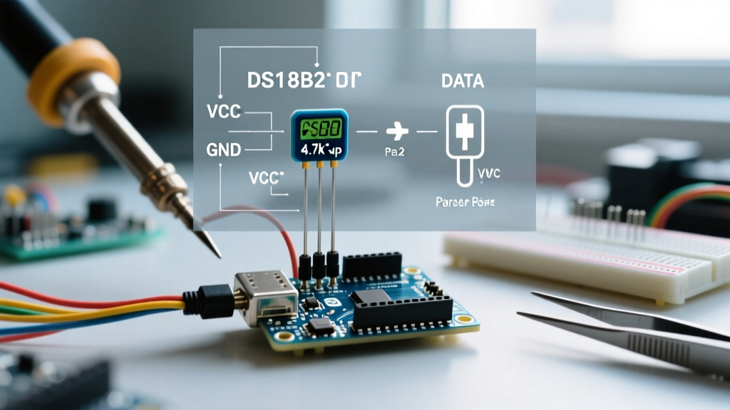
Modern compact modules like the Beitian BN-220 or the u-blox CAM-M8Q support both UART and I2C (DDC) simultaneously. However, if you are using an Arduino with limited serial ports and attempt to read the GPS via the I2C Wire library, you must ensure the pull-up resistors on the SDA/SCL lines are correctly sized. Many breakout boards include 10kΩ pull-ups, which are too weak for long wire runs or fast I2C clocks (400kHz), resulting in NAK (Not Acknowledged) errors. If you experience I2C lockups, add external 4.7kΩ pull-up resistors to the 3.3V rail.
Summary Diagnostic Flowchart
Follow this sequential path when your GPS fails to initialize:
- Power Check: Measure VCC at the GPS module pins with a multimeter while acquiring satellites. Must remain >3.1V.
- Raw Serial Check: Bypass all libraries. Write a simple sketch that reads from the GPS serial port and prints directly to the USB Serial. Do you see raw
$GPtext? - Baud Rate Match: If raw text is gibberish, cycle through 9600, 115200, and 38400 in your sketch until the text becomes readable.
- Environment Check: Take the entire rig outside. Wait a minimum of 5 minutes for the almanac download.
- Library Integration: Once raw text is verified outdoors, re-introduce TinyGPS++ and monitor checksum failure rates.
By systematically isolating power, physical layer serial timing, and protocol parsing, you can resolve 99% of module gps arduino integration errors without resorting to replacing hardware.