
The Anatomy of a Cable Arduino USB Connection
At first glance, connecting a microcontroller to a computer seems trivial. However, the physical layer of your development environment is often the primary point of failure. Understanding your cable Arduino USB setup is critical because the cable does not merely supply 5V power; it acts as a high-frequency differential signaling bridge. When a sketch fails to upload or the serial monitor outputs garbage characters, the root cause frequently lies in wire gauge, shielding, or internal pinout configurations rather than the code itself.
In 2026, the maker ecosystem features a fragmented mix of legacy and modern connector standards. While the Arduino Uno R4 and Nano ESP32 have largely standardized around USB Type-C, millions of legacy boards (Uno R3, Mega 2560) and third-party clones still rely on Type-B, Mini-B, and Micro-B connectors. This guide dissects the electrical realities of these connections, providing actionable diagnostics for persistent upload and serial communication failures.
Mapping the Connector Ecosystem
Different microcontrollers utilize different physical interfaces, each with distinct mechanical and electrical characteristics. Below is a comparison matrix of the most common connectors you will encounter in the wild.
| Connector Type | Common Boards | Pins | Mechanical Durability | Max Power Delivery (Standard) |
|---|---|---|---|---|
| USB Type-B | Uno R3, Mega 2560 | 4 | High (Friction lock) | 5V / 500mA (USB 2.0) |
| USB Mini-B | Nano V2, LilyPad | 5 | Low (Prone to wobble) | 5V / 500mA |
| USB Micro-B | MKR WiFi 1010, ESP32 Clones | 5 | Medium (Snap fit) | 5V / 1.8A (USB BC 1.2) |
| USB Type-C | Uno R4, Nano ESP32 | 24 | Very High (Reversible) | 5V-20V / Up to 3A+ |
Note: While USB Type-C supports USB Power Delivery (PD) for high-wattage applications, standard Arduino boards negotiate a baseline 5V profile. Attempting to draw excessive current through the board's linear voltage regulator (like the NCP1117 on the Uno R3) will cause thermal shutdown, regardless of the cable's capability.
The 'Charge-Only' Trap: Power vs. Data Wiring
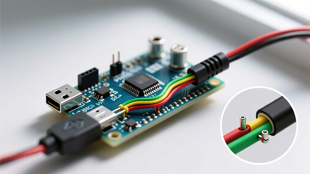
The single most common reason for a 'Port Not Found' error in the Arduino IDE is the use of a charge-only cable. Standard USB 2.0 cables contain four internal wires:
- VBUS (Red): +5V Power
- GND (Black): Ground
- D- (White): Data Minus
- D+ (Green): Data Plus
Manufacturers of cheap promotional cables (often included with budget desk fans or LED strips) omit the D- and D+ wires to save on copper costs. These cables will successfully power the Arduino's onboard LED, leading the user to falsely believe the hardware is functioning and recognized by the PC.
How to Test for Data Lines with a Multimeter
Set your digital multimeter to continuity mode. For a standard USB Type-A to Type-B cable, probe the pins on the Type-A connector:
- Pin 1 (Outer Left): VBUS
- Pin 2 (Inner Left): D-
- Pin 3 (Inner Right): D+
- Pin 4 (Outer Right): GND
Match these against the corresponding pins on the Micro-B or Type-B end. If Pins 2 and 3 do not trigger a continuity beep, the cable is charge-only and must be discarded for development purposes.
Inside the Board: USB-to-Serial Converter Chips
The USB cable does not connect directly to the main microcontroller (e.g., the ATmega328P). Instead, it interfaces with a secondary bridge IC that translates USB differential signals into TTL serial (TX/RX). Identifying which chip your board uses is vital for driver troubleshooting.
ATmega16U2 vs. CH340G vs. CP2102
- ATmega16U2 (Official Boards): Found on genuine Arduino Uno R3 and Mega 2560 boards. This is a dedicated AVR microcontroller programmed to act as a USB-to-Serial bridge. It requires no special drivers on Windows 10/11, macOS, or Linux, as it utilizes native CDC/ACM class protocols.
- CH340G / CH340C (Clone Boards): The standard for budget-friendly clones. The CH340G requires an external 12MHz crystal, while the CH340C has it integrated. Historically, this chip required manual driver installation on Windows and macOS. As of 2026, Windows 11 and macOS Sonoma/Sequoia include signed WCH drivers natively, though older legacy systems still require the SparkFun serial driver package.
- CP2102 / CP2104 (Silicon Labs): Commonly found on NodeMCU and third-party ESP32 development boards programmed via the Arduino IDE. These are highly reliable but occasionally conflict with generic Windows CDC drivers, requiring the official Silicon Labs CP210x VCP drivers.
Expert Insight: If your CH340-based clone is recognized in Device Manager but throws anavrdude: ser_open(): can't open deviceerror, the issue is rarely the cable. It is usually a baud rate mismatch or a permissions issue on Linux. Runsudo usermod -a -G dialout $USERto grant your user profile access to the serial port, then reboot.
Signal Integrity, Length, and Degradation
USB 2.0 specifies a maximum theoretical cable length of 5 meters. However, the USB Implementers Forum (USB-IF) documentation assumes high-quality, shielded twisted-pair wiring. In practical maker environments, long, unshielded cables introduce capacitance and electromagnetic interference (EMI) that corrupt the 115200 baud serial handshake required for sketch uploads.
Wire Gauge Matters
High-quality USB cables utilize AWG 28 for the data lines and AWG 24 (or thicker) for the power lines. Budget cables often use AWG 30 or thinner for all lines. When powering an Arduino equipped with a motor shield or multiple servos, a thin VBUS wire will suffer from severe voltage drop. If the voltage at the board's USB VBUS pin dips below 4.3V during a servo actuation, the ATmega16U2 bridge chip will brownout and reset, severing the USB connection mid-upload.
Best Practice: Keep passive USB cables under 2 meters for reliable firmware flashing. If you must route a cable 5+ meters to a remote sensor station, use an active USB repeater cable with a built-in signal conditioning hub.
Step-by-Step Troubleshooting Flow
When facing connection issues, follow this strict diagnostic hierarchy to isolate the fault. For deeper hardware initialization steps, refer to the official Arduino getting started documentation.
- Verify Physical Recognition:
- Windows: Open Device Manager. Look under 'Ports (COM & LPT)' or 'Other Devices'. A yellow exclamation mark indicates a driver failure, not a bad cable.
- macOS: Open Terminal and type
ls /dev/tty.usb*. If the device appears, the data lines are intact. - Linux: Type
dmesg | grep ttyimmediately after plugging in the board to watch the kernel assign the/dev/ttyUSB0or/dev/ttyACM0node.
- Eliminate the Hub: Unplug the Arduino from any unpowered USB hubs or front-panel PC case headers. Connect directly to the motherboard's rear I/O panel to ensure stable 5V rail delivery.
- Check for Peripheral Backfeeding: Disconnect all shields, jumper wires, and sensors. A short circuit on a digital pin (especially Pin 0/RX or Pin 1/TX) will prevent the USB bridge from asserting the reset line via the DTR capacitor.
- Swap the Cable: Substitute the current cable with a verified data-capable cable from a reputable brand (e.g., Anker, Belkin, or UGREEN). Gas station and dollar-store cables should never be used for development.
Summary
Treating your USB cable as a mere accessory is a critical mistake in embedded systems development. By understanding the pinout differences, recognizing the limitations of USB-to-Serial bridge ICs, and respecting the physics of signal degradation over copper, you can eliminate hours of frustrating IDE errors. Invest in high-quality, shielded, data-capable cables, and label them clearly to ensure they never get mixed up with your drawer of charge-only power cords.