
The Core Dilemma: 5V vs 3.3V Logic Architectures
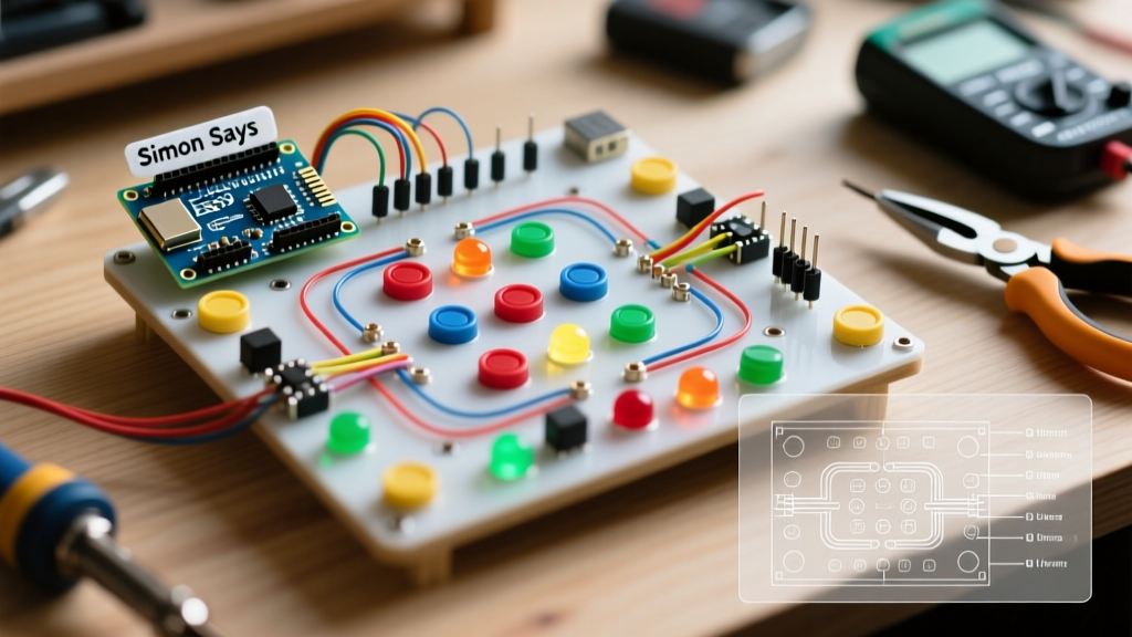
Building a Simon Says memory game is a rite of passage in the maker community. Originally popularized by Milton Bradley in the late 1970s, the patent has long since expired, paving the way for countless open-source hardware clones. However, as we navigate the electronics landscape in 2026, the transition from legacy 5V microcontrollers to modern 3.3V architectures introduces severe compatibility pitfalls. A mismatched component can result in erratic button reads, dim LEDs, or permanently damaged GPIO pins. This compatibility guide dissects the exact hardware pairings required to build a robust, production-grade Simon Says Arduino project.
Expert Insight: The most common point of failure in DIY Simon games is not the code logic, but the physical layer—specifically, floating inputs and logic-level mismatches between 3.3V microcontrollers and 5V addressable LEDs.
Microcontroller Board Compatibility Matrix
Choosing the right brain for your Simon Says unit dictates your entire bill of materials (BOM). Below is a compatibility matrix comparing popular boards available in 2026, focusing on I/O availability, logic levels, and audio capabilities.
| Microcontroller Board | Logic Level | Native Audio (PWM) | I/O Pins Available | Best Use Case |
|---|---|---|---|---|
| Arduino Uno R4 Minima | 5V | Excellent (12-bit DAC) | 14 Digital, 6 Analog | Traditional through-hole builds, 5V NeoPixels |
| Arduino Nano ESP32 | 3.3V | Good (LEDC API) | 14 Digital, 8 Analog | IoT-enabled Simon, Wi-Fi high-score logging |
| Seeed XIAO ESP32C3 | 3.3V | Limited | 11 Digital, 4 Analog | Ultra-compact, wearable, or PCB-integrated designs |
| ATtiny85 (DIP-8) | 5V | Basic (Timer1) | 5 Digital/Analog | Minimalist, low-power standalone cartridges |
For beginners, the Arduino Uno R4 Minima (retailing around $20) remains the most forgiving due to its 5V logic, which natively interfaces with standard 5mm LEDs and 5V buzzers without level shifters. For advanced makers building connected arcade cabinets, the Nano ESP32 is superior, provided you adapt your component choices to 3.3V logic.
Input Interfaces: Switches, Touch, and Voltage Ladders
The Simon Says game relies on four distinct inputs. How you wire these inputs drastically affects your code complexity and hardware footprint.
1. Standard Tactile Switches (6x6mm)
The most common approach. You must use pull-up or pull-down resistors to prevent floating pins, which cause phantom button presses. According to SparkFun's pull-up resistor guide, a 10kΩ resistor is the industry standard. However, to save breadboard space, utilize the microcontroller's internal pull-ups by initializing the pins with pinMode(buttonPin, INPUT_PULLUP);. This inverts your logic (LOW means pressed), but eliminates four external resistors.
2. Capacitive Touch Sensors (TTP223)
For a sleek, button-less acrylic faceplate, TTP223 modules are ideal. Compatibility Warning: Most TTP223 modules operate between 2.0V and 5.5V, making them universally compatible with both 5V and 3.3V boards. Ensure you configure the module for toggle or momentary mode via the A/B jumper pads on the PCB before soldering.
3. Resistive Voltage Ladders (ATtiny85 Specific)
If you are using an ATtiny85 and lack the GPIO pins for four separate buttons, you can wire four switches in a series-parallel resistor ladder, feeding a single analog pin. This requires precise 1% tolerance resistors (e.g., 1kΩ, 2.2kΩ, 4.7kΩ, 10kΩ) and analog threshold mapping in your sketch.
Output Stages: LEDs, NeoPixels, and Audio
Standard 5mm Through-Hole LEDs
If using standard diffused LEDs, you must calculate the current-limiting resistor based on your board's logic level. Assuming a standard red LED with a forward voltage ($V_f$) of 2.0V and a target current ($I$) of 20mA:
- For 5V Boards (Uno R4): $R = (5V - 2.0V) / 0.02A = 150Ω$. Use a standard 150Ω or 220Ω resistor.
- For 3.3V Boards (Nano ESP32): $R = (3.3V - 2.0V) / 0.02A = 65Ω$. Use a standard 68Ω resistor. Using a 220Ω resistor here will result in visibly dim LEDs.
Addressable RGB LEDs (WS2812B / NeoPixels)
Upgrading to NeoPixels allows for dynamic color shifts (e.g., turning all LEDs red when the player loses). However, WS2812B chips require a 5V data signal to reliably register the 'HIGH' state. As detailed in the Adafruit NeoPixel Uberguide, feeding a 3.3V data signal from an ESP32 directly to a 5V NeoPixel strip will cause erratic flickering or total failure. Solution: Route the ESP32 data pin through a 74AHCT125 level shifter, powered by 5V, before it hits the LED DIN pin.
The Buzzer Gotcha: tone() vs ledcWriteTone()
Audio feedback is mandatory for Simon Says. The compatibility gap here is massive between AVR and ESP32 architectures.
- AVR (Uno/Nano): You use the standard
tone(pin, frequency, duration)function. Note that on older AVR chips, this function hijacks Timer2, which will break PWM functionality on pins 3 and 11. The official Arduino tone() documentation outlines these timer conflicts. - ESP32 (Nano ESP32 / XIAO): The legacy
tone()function is deprecated or highly unstable on modern ESP32 Arduino cores. You must use the LEDC (LED Control) peripheral API. Initialize withledcAttach(pin, freq, resolution)and trigger audio withledcWriteTone(pin, frequency). Use a passive buzzer, as active buzzers have internal oscillators and will not respond to PWM frequency changes.
Power Delivery and Edge Cases
A common failure mode in Simon Says builds occurs when the player hits a 'win' state, triggering all four LEDs and the buzzer simultaneously. Four standard LEDs (20mA each) plus a passive buzzer (30mA) draw roughly 110mA. While this is well within the 500mA limit of a standard USB 2.0 port, if you upgrade to NeoPixels, four white LEDs at full brightness will draw 240mA (60mA each).
Edge Case: If you are powering the game via a 9V battery clipped to the Uno's barrel jack, the onboard linear voltage regulator will overheat and shut down when drawing more than 150mA. Always power NeoPixel-based Simon games via the 5V USB pin or a dedicated 5V 2A buck converter wired directly to the LED VCC rail.
Summary Checklist for a Flawless Build
- Verify Logic Levels: Match 5V sensors/LEDs with 5V boards, or use a 74AHCT125 level shifter for 3.3V boards.
- Enable Internal Pull-ups: Save space and wiring by using
INPUT_PULLUPfor tactile switches. - Recalculate Resistors: Do not blindly use 220Ω resistors if you switch from a 5V Uno to a 3.3V ESP32.
- Update Audio Code: Migrate from
tone()toledcWriteTone()when moving to ESP32 architectures. - Isolate Power: Bypass the onboard linear regulator for high-current LED arrays by injecting 5V directly from a quality USB power supply.
By respecting the electrical characteristics of your chosen microcontroller and matching your passive and active components accordingly, your Simon Says Arduino project will transition from a buggy breadboard prototype to a reliable, arcade-quality desktop game.