
The Anatomy of a Floating Arduino Pin
If you have ever wired a simple pushbutton to an Arduino Uno, only to see the Serial Monitor spit out a chaotic stream of random 1s and 0s when the button is not pressed, you have encountered a floating pin. Microcontroller GPIO (General Purpose Input/Output) pins, including those on the ATmega328P, ESP32, and RP2040, feature extremely high-impedance CMOS inputs. According to the official Arduino digital pins documentation, an unconnected pin has an input impedance in the megaohm range, meaning it requires almost zero current to change its logic state.
Because of this high impedance, a floating pin acts like a tiny antenna. It picks up electromagnetic interference (EMI) from nearby AC mains wiring, switching power supplies, and even your own body's electrostatic field. To force the pin into a known, stable state (HIGH) when the switch is open, we use a pull-up resistor. This guide provides a comprehensive troubleshooting framework for diagnosing and fixing floating pin issues using both internal and external pull-up resistor Arduino configurations.
Diagnostic Checklist: Is Your Pin Floating?
Before soldering new components or rewriting your sketch, run through this diagnostic flow to confirm the root cause of your erratic readings:
- Symptom: Digital input reads randomly fluctuating HIGH/LOW when the circuit is physically untouched.
- Symptom: I2C sensors (like the BME280 or MPU6050) fail to initialize or return
NaN/0xFFvalues on the I2C scanner. - Symptom: Interrupts trigger falsely without mechanical switch actuation.
- Hardware Check: Use a multimeter to measure the voltage between the GPIO pin and GND. If the voltage hovers unpredictably between 0.5V and 2.5V (on a 5V board) when the switch is open, the pin is floating.
- Wiring Check: Verify that your switch is wired between the GPIO pin and GND, not between VCC and the GPIO pin (which would require a pull-down resistor instead).
Fix 1: Enabling Internal Pull-Up Resistors (Software)
For standard pushbuttons, limit switches, and rotary encoders located within a few centimeters of the microcontroller, you rarely need external components. Modern microcontrollers feature built-in pull-up resistors that can be activated via software.
On the classic ATmega328P (Arduino Uno/Nano), the internal pull-up resistance is typically between 20kΩ and 50kΩ. On the ESP32, it is approximately 45kΩ, while the RP2040 (Raspberry Pi Pico) features internal pull-ups in the 50kΩ to 80kΩ range.
The Correct Code Implementation
Legacy Arduino code often used a two-step process to enable internal pull-ups, which is now deprecated. Do not use pinMode(pin, INPUT); followed by digitalWrite(pin, HIGH);. Instead, use the dedicated INPUT_PULLUP constant:
const int buttonPin = 2;

void setup() {
  Serial.begin(115200);
  // Correctly enables the internal 20k-50k pull-up resistor
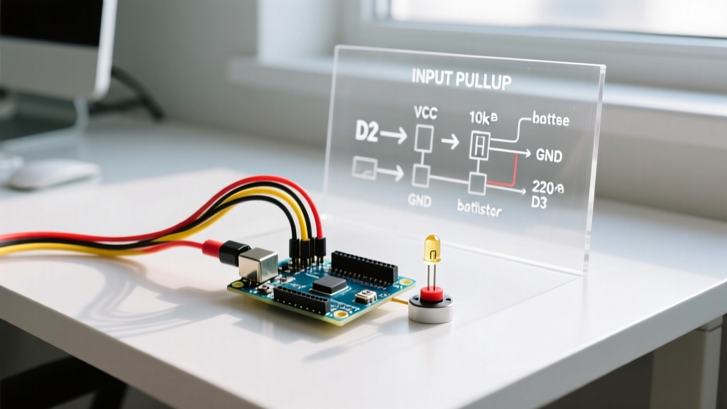
  pinMode(buttonPin, INPUT_PULLUP);
}

void loop() {
  // Note: The logic is inverted.
  // Pressed = LOW (connected to GND), Unpressed = HIGH (pulled to VCC)
  int buttonState = digitalRead(buttonPin);
  Serial.println(buttonState);
  delay(50);
}
Pro-Tip for ESP32 Users: The ESP32 also supports internal pull-down resistors via INPUT_PULLDOWN. However, the ATmega328P does not have internal pull-downs. If you require active-HIGH logic on an Uno, you must use an external pull-down resistor.
Fix 2: Sizing External Pull-Up Resistors (Hardware)
Internal pull-ups are convenient, but their high resistance (weak pull) makes them unsuitable for specific real-world scenarios. You must solder an external pull-up resistor when dealing with long wire runs, electrically noisy environments (like inside a CNC machine or near variable frequency drives), or high-speed communication buses.
Calculating the Optimal Resistor Value
The goal of an external pull-up is to provide enough current to quickly charge the parasitic capacitance of the wire and pin, pulling the voltage to VCC rapidly, without drawing excessive current when the switch closes (connecting the pin to GND).
Use Ohm's Law: R = V / I
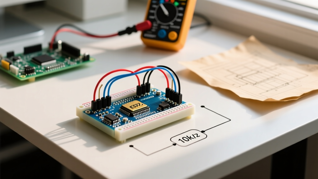
- Standard Switches (Short Wires): 10kΩ is the industry standard. At 5V, this draws 0.5mA when the button is pressed, which is safe for any MCU GPIO and provides a solid logic HIGH.
- Long Wires / Noisy Environments: Use 4.7kΩ or even 2.2kΩ. Long cables (e.g., 24 AWG wire over 3 meters) act as capacitors and antennas. A stronger pull-up (lower resistance) overcomes 50/60Hz mains hum and ensures the voltage stays firmly above the 2.0V logic HIGH threshold of the ATmega328P.
- Battery-Powered Devices: Use 47kΩ to 100kΩ to minimize current draw when the button is held down, preserving battery life at the cost of increased susceptibility to EMI.
Internal vs. External Pull-Up Comparison Matrix
| Feature | Internal Pull-Up (Software) | External Pull-Up (Hardware) |
|---|---|---|
| Typical Resistance | 20kΩ - 80kΩ (MCU dependent) | 1kΩ - 100kΩ (Designer chosen) |
| Board Space / BOM Cost | Zero (Built into silicon) | Requires physical through-hole/SMD resistor |
| Noise Immunity (EMI) | Poor (Weak pull, susceptible to long wires) | Excellent (Can use 2.2kΩ for strong pull) |
| Switch Current Draw (at 5V) | ~0.1mA to 0.25mA | ~0.5mA (for 10kΩ) to 2.2mA (for 2.2kΩ) |
| Best Use Case | Simple UI buttons, short traces, prototyping | I2C buses, long cable runs, industrial relays |
Edge Case Troubleshooting: I2C Bus Lockups
The most critical application of the pull-up resistor in the Arduino ecosystem is the I2C (Inter-Integrated Circuit) bus. I2C uses an open-drain architecture. The SDA (data) and SCL (clock) lines are actively pulled LOW by devices, but they are never actively driven HIGH. They rely entirely on pull-up resistors to return to the HIGH state.
If you are troubleshooting an I2C sensor that randomly drops off the bus or causes the Arduino to hard-lock, the pull-up resistors are almost always the culprit. According to the official NXP I2C-bus specification (UM10204), the pull-up resistor value must be carefully matched to the bus capacitance (Cb) and the desired clock speed.
- Standard Mode (100 kHz): Use 4.7kΩ pull-ups on both SDA and SCL to 5V (or 3.3V).
- Fast Mode (400 kHz): The rise time must be faster. Drop the pull-up resistors to 2.2kΩ or even 1kΩ to overcome the parasitic capacitance of multiple sensors wired in parallel.
Fixing the Lockup: Many cheap I2C sensor modules (like the GY-521 or generic OLED displays) include onboard 4.7kΩ pull-up resistors. If you wire three of these modules together, you are placing three 4.7kΩ resistors in parallel, resulting in an equivalent resistance of ~1.5kΩ. While this creates a very strong pull-up, it may exceed the 3mA sink current limit of some microcontroller GPIO pins when pulling the bus LOW, potentially damaging the ATmega328P or causing logic level failures. Always check module schemematics and remove redundant jumper-pad resistors if wiring multiple I2C devices.
How to Verify Pull-Up Integrity with a Multimeter
Do not rely solely on code to verify your hardware. Use a digital multimeter (DMM) to physically confirm the pull-up resistor is functioning:
- Set your DMM to measure DC Voltage.
- Connect the black probe to the Arduino GND pin.
- Connect the red probe to the GPIO pin wired to your switch (with the switch open/unpressed).
- Expected Reading: You should read exactly VCC (e.g., 4.95V to 5.05V on a USB-powered Uno, or 3.28V on an ESP32). If you read 0V, your pull-up is missing or disabled. If you read a fluctuating value between 1V and 3V, your pull-up is too weak for the environmental noise, or your wire is broken.
- Press and hold the switch. The voltage should immediately drop to 0.00V - 0.05V. If it only drops to 0.5V or higher, you have a high-resistance ground fault or a failing mechanical switch.
Frequently Asked Questions
Can I use a pull-up resistor on an analog pin?
Yes. On the Arduino Uno, pins A0 through A5 double as digital GPIO pins (D14 through D19). You can configure them as INPUT_PULLUP for digital switches. However, if you are reading an analog sensor (like a potentiometer or photoresistor), the sensor itself usually acts as part of a voltage divider, and adding a parallel pull-up resistor will skew your analog readings by altering the equivalent resistance of the circuit.
Why is my button reading inverted (LOW when pressed)?
This is the natural behavior of a pull-up configuration. The resistor pulls the pin to VCC (HIGH). When you press the button, you create a path of least resistance directly to GND, pulling the pin to 0V (LOW). If your logic requires a HIGH signal upon pressing, simply invert the reading in software: bool isPressed = !digitalRead(buttonPin);.
What is the difference between a pull-up and a pull-down resistor?
A pull-up resistor connects the GPIO pin to VCC, keeping the default state HIGH. A pull-down resistor connects the pin to GND, keeping the default state LOW. As noted in the SparkFun pull-up resistor tutorial, pull-ups are vastly preferred in microcontroller design because most MCUs (including the ATmega328P) have internal pull-ups, but lack internal pull-downs, saving you physical board space and component costs.