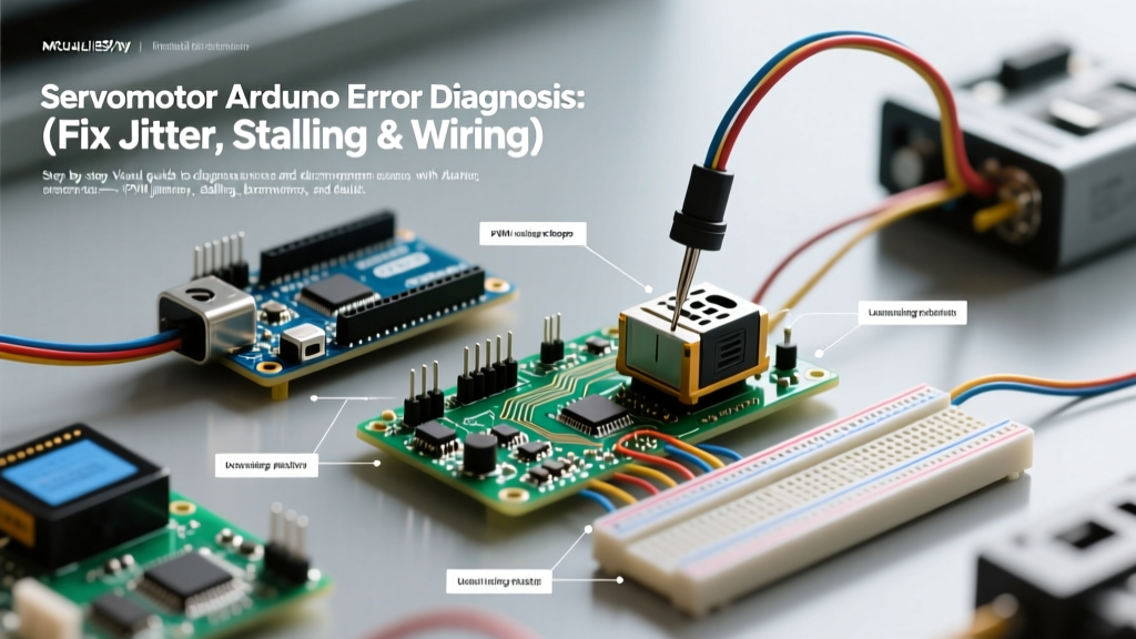

The Anatomy of Servomotor Arduino Failures
Integrating a servomotor Arduino setup is a rite of passage for robotics and automation makers. Unlike standard DC motors, RC servos are closed-loop systems containing a DC motor, a gear train, and a feedback potentiometer. When you command a position via the Arduino IDE, the internal H-bridge drives the motor until the potentiometer's voltage matches the incoming PWM pulse width. However, this closed-loop architecture makes servos highly susceptible to power starvation, signal noise, and timer interrupt conflicts.
In 2026, with the widespread adoption of high-torque metal-gear servos and the transition from legacy AVR boards to the Arduino R4 and ESP32 ecosystems, the nature of servo errors has evolved. A twitching TowerPro SG90 or a stalling MG996R is rarely a 'broken servo'—it is almost always a systemic diagnostic failure in power delivery, PWM signal integrity, or code-level timer mapping. This guide provides deep-level error diagnosis to resolve these exact hardware and software bottlenecks.
Power Delivery Bottlenecks: Brownouts and Stalling
The most catastrophic and common error in a servomotor Arduino project is attempting to power the servo directly from the Arduino's 5V pin. When a servo starts moving, or worse, when it stalls against a mechanical load, it draws its peak stall current. If this current exceeds the Arduino's onboard voltage regulator or USB port limits, the voltage sags below the microcontroller's Brown-Out Detection (BOD) threshold (typically 4.3V for the ATmega328P), causing an immediate system reset.
Servo Stall Current & Power Requirements Matrix
| Servo Model (2026 Market Std.) | Stall Torque (6.0V) | Peak Stall Current | Min. Wire Gauge | Recommended External BEC |
|---|---|---|---|---|
| TowerPro SG90 (Micro) | 1.8 kg-cm | 0.7A - 1.0A | 26 AWG | 5V / 1A Linear LDO |
| MG90S (Metal Micro) | 2.2 kg-cm | 1.2A - 1.5A | 24 AWG | 5V / 2A Buck Converter |
| MG996R (Standard High-Torque) | 13 kg-cm | 2.5A | 22 AWG | 6V / 3A Switching BEC |
| DS3218 (Large Digital) | 20 kg-cm | 3.0A - 3.5A | 18 AWG | 6V-7.4V / 5A UBEC |
The Decoupling Capacitor Fix
Even with an external Battery Eliminator Circuit (BEC), long wire runs introduce inductance. When the servo's internal motor commutates, it creates high-frequency voltage spikes. To stabilize the power rail, you must solder a low-ESR (Equivalent Series Resistance) electrolytic capacitor directly across the servo's VCC and GND wires at the connector. A 470µF to 1000µF capacitor rated for 10V or higher acts as a local energy reservoir, supplying the instantaneous current spike during startup and preventing the Arduino's logic from browning out.
PWM Signal Integrity: Diagnosing Jitter and Twitching
RC servos expect a precise 50Hz PWM signal (a 20ms period). The pulse width dictates the position: typically 1000µs (1ms) for 0°, 1500µs for 90°, and 2000µs for 180°. If your servo is jittering randomly while holding a position, the Arduino is failing to deliver a consistent pulse width.
Timer Interrupt Conflicts
On legacy AVR boards (like the Uno R3), the standard Arduino Servo Library relies on Timer1 to generate these 50Hz interrupts. If your sketch simultaneously uses libraries that depend on Timer1—such as IRremote, TimerOne, or certain fast-PWM motor control libraries—the servo interrupt will be delayed. A delay of just 20µs translates to physical jitter in a high-resolution digital servo.
Expert Diagnostic Tip: If you are using an Arduino Uno R3 and notice that analogWrite() stops working on Pins 9 and 10 after attaching a servo, this is not a bug. The Servo library has hijacked Timer1, which controls hardware PWM on those specific pins. Upgrade to the Arduino R4 Minima or use an ESP32, which utilizes dedicated hardware PWM channels (LEDC peripheral) that do not conflict with CPU timers.
The I2C Offload Solution
For complex robotic arms or multi-servo hexapods, generating multiple 50Hz signals via software interrupts is a recipe for jitter. The industry-standard fix in 2026 is to use a PCA9685 16-Channel PWM Driver. This ~$8 I2C chip features its own dedicated hardware oscillator. You simply send an I2C command from the Arduino (e.g., pwm.setPWM(0, 0, 350)), and the PCA9685 handles the continuous 50Hz pulse generation flawlessly, freeing the Arduino's CPU for kinematics calculations and sensor polling.
The 'Floating Ground' Wiring Fault
A frequent error diagnosis scenario involves a servo that moves erratically or sweeps to its maximum limit immediately upon uploading a sketch. This is almost always a missing common ground. The PWM signal wire (usually white or yellow) carries a voltage pulse relative to a ground reference. If you power the servo from an external 6V battery pack but only connect the signal wire to the Arduino GPIO pin—leaving the battery's GND disconnected from the Arduino's GND—the signal is 'floating'. The Arduino's 5V logic pulse is interpreted as random noise by the servo's internal comparator, causing violent, gear-stripping sweeps.
The Fix: Always run a dedicated ground wire from the external power supply's negative terminal directly to one of the Arduino's GND pins. For high-current setups (like the DS3218), use a star-ground topology where the Arduino GND and Servo GND meet at a single physical point on the power distribution board to prevent ground loops and back-EMF interference.
Mechanical Over-Travel and Potentiometer Burnout
Servos have physical hard stops. If your code commands a position beyond the physical travel of the internal potentiometer, the H-bridge will continuously apply full voltage to the motor, trying to reach an impossible target. This results in a loud humming noise, rapid overheating, and eventual burnout of the internal wiper track or stripped nylon/metal gears.
Calibrating Limits via Code
Never rely on the default servo.write(0) or servo.write(180) without physical verification. Manufacturing tolerances mean a 0° command might actually demand 950µs, while the servo's physical stop is at 1050µs. Instead, use the attach() function with custom microsecond limits, or use writeMicroseconds() to map the exact safe boundaries of your specific unit.
// Safe attachment preventing over-travel on an MG996R
// Syntax: attach(pin, min_us, max_us)
myServo.attach(9, 550, 2450);
By explicitly defining the minimum and maximum pulse widths in the attach() function, you create a software hard-stop that protects the mechanical gears and prevents the stall-current overheating issue.
High-Voltage (HV) Servo Logic Level Warnings
Modern brushless and high-torque HV servos (operating at 7.4V to 8.4V for 2S LiPo setups) are increasingly common in advanced Arduino robotics. Critical Warning: While these servos can handle 8.4V on their power rails, their signal input pins are often only 5V tolerant. If you are using a 3.3V Arduino board (like the Arduino Nano 33 BLE or ESP32), the 3.3V PWM signal may not be recognized as a valid 'HIGH' by an 8.4V servo's internal optocoupler, leading to total unresponsiveness. Conversely, feeding a 5V signal into a poorly designed HV servo signal line can fry the internal MCU. Always use a bidirectional logic level shifter or a dedicated opto-isolated servo driver board when mixing 3.3V logic with 7.4V+ servo power rails.
Rapid Diagnostic Troubleshooting Matrix
| Observed Symptom | Probable Root Cause | Multimeter / Scope Test | Corrective Action |
|---|---|---|---|
| Arduino resets when servo moves | Voltage brownout / USB current limit | Measure 5V pin during servo actuation; look for drops below 4.5V | Implement external 3A BEC and 1000µF decoupling capacitor |
| Random micro-jitters at rest | Timer1 interrupt conflict or USB noise | Oscilloscope: Check for pulse width variance >10µs | Switch to PCA9685 I2C driver; use twisted-pair signal wiring |
| Servo sweeps violently to max limit | Floating ground reference | Continuity test between Servo GND and Arduino GND | Connect external power GND directly to Arduino GND |
| Loud humming, motor gets hot | Commanded position exceeds physical hard-stop | Measure current draw; >1.5A indicates stall | Recalibrate limits using attach(pin, min, max) |
| Servo completely unresponsive | Logic level mismatch (3.3V vs 5V/8.4V) | Verify GPIO HIGH voltage matches servo logic threshold | Insert logic level shifter or MOSFET gate driver |
Summary
Diagnosing a servomotor Arduino setup requires looking beyond the code and treating the system as an integrated electromechanical circuit. By ensuring robust power delivery via external switching BECs, eliminating timer conflicts through hardware PWM offloading, and strictly maintaining common-ground references, you can eliminate 99% of servo jitter and stalling errors. Always respect the stall current ratings of modern high-torque servos, and calibrate your microsecond boundaries to protect the internal feedback potentiometers from mechanical destruction.