
The Anatomy of an Arduino Alarm Clock Failure
Building a custom Arduino alarm clock is a rite of passage for microcontroller enthusiasts. It seems simple enough: wire up a Real Time Clock (RTC) module, connect a buzzer, write a few lines of logic to compare the current time against a target wake time, and go to sleep. However, when you deploy the device on your nightstand, the reality of embedded systems engineering quickly sets in. You wake up at 7:14 AM instead of 7:00 AM, or worse, the microcontroller remains in a comatose sleep state while you sleep through your morning meetings.
Troubleshooting an Arduino alarm clock requires moving beyond basic syntax errors and diving into hardware-level physics, I2C bus integrity, and AVR power management architectures. In this comprehensive fix guide, we will dissect the four most critical failure modes of DIY alarm clocks and provide exact, actionable solutions to ensure your device triggers reliably down to the second.
RTC Drift: Why Your Alarm is Chronologically Compromised
The most common complaint with homemade timekeeping projects is clock drift. If your alarm consistently triggers three to five minutes late over the course of a month, your RTC module is the culprit. Most beginner kits include the DS1307 RTC module. While the DS1307 is cheap (often under $1.50 on bulk marketplaces), it relies on an external 32.768 kHz tuning-fork crystal oscillator that is highly sensitive to ambient temperature fluctuations.
The Temperature Coefficient Problem
Tuning-fork crystals exhibit a parabolic temperature coefficient, typically around -0.034 ppm/°C². If your bedroom drops from 25°C to 15°C at night, the DS1307 oscillator slows down, losing seconds every day. By the end of the month, your Arduino alarm clock is chronologically compromised.
The Fix: Upgrade to the DS3231SN
To achieve true reliability, you must upgrade to the DS3231SN (the SOIC-16 package version, not the cheaper MEMS-based DS3231MZ which has slightly different aging characteristics). The DS3231SN integrates a temperature-compensated crystal oscillator (TCXO) and a digital temperature sensor that adjusts the oscillator frequency every 64 seconds. According to the Analog Devices DS3231 datasheet, this maintains accuracy within ±2 ppm from 0°C to +40°C, translating to roughly 1 minute of drift per year.
| Module | Accuracy | Temp Compensation | Avg. Price (2026) | Verdict |
|---|---|---|---|---|
| DS1307 | ±20 ppm (varies wildly) | None | $1.20 | Unsuitable for alarms |
| DS3231MZ (MEMS) | ±5 ppm | Internal MEMS | $2.50 | Good, but aging drift |
| DS3231SN (Crystal) | ±2 ppm | TCXO Integrated | $3.80 | Best for precision alarms |
I2C Bus Noise and the 'Phantom Alarm' Phenomenon
Does your Arduino alarm clock occasionally trigger at 3:14 AM for no apparent reason? This 'phantom alarm' is almost always caused by I2C bus noise corrupting the data payload when the ATmega328P polls the RTC for the current time. If a bit-flip occurs on the SDA line during the minutes register read, the microcontroller might read '14' instead of '00', triggering the buzzer prematurely.
Fixing the I2C Pull-Up Architecture
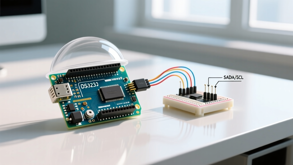
The I2C protocol uses open-drain outputs. Without adequate pull-up resistors, the SDA and SCL lines float, acting as antennas for electromagnetic interference (EMI) generated by nearby switching power supplies or Wi-Fi routers. The NXP I2C-bus specification mandates specific pull-up values based on bus capacitance.
- Wire Length: Keep I2C traces or jumper wires under 10cm. Long wires increase bus capacitance, ruining the rise-time of the signals.
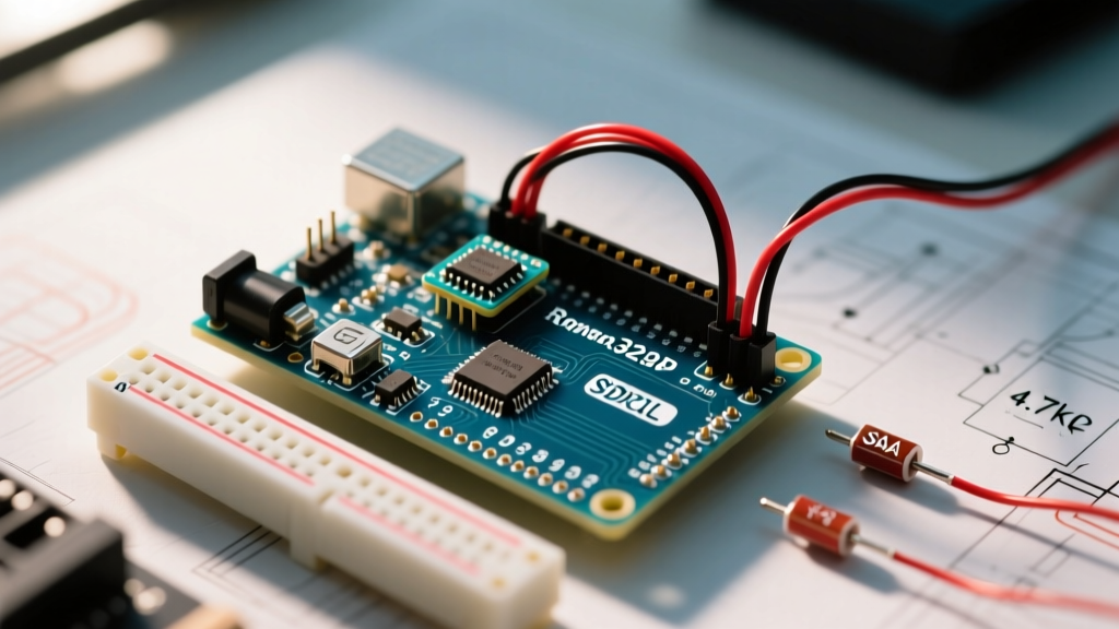
- Pull-Up Resistors: Most cheap RTC modules include 10kΩ pull-ups, which are too weak for noisy environments. Desolder them and install 4.7kΩ or even 2.2kΩ resistors tied to the 3.3V or 5V logic rail (matching your microcontroller's VCC).
- Twisted Pair: If you must run wires across a breadboard, twist the SDA and SCL wires together to reject common-mode noise.
Sleep Mode Bugs: When the ATmega328P Refuses to Wake
To prevent your alarm clock from draining a 9V battery in three days, you must put the Arduino into SLEEP_MODE_PWR_DOWN. However, a frequent failure mode is the microcontroller ignoring the RTC's wake-up signal. This happens because developers misunderstand how the DS3231's SQW/INT pin interacts with the ATmega's external interrupt vectors.
The SQW/INT Pin Configuration Sequence
By default, the DS3231 outputs a square wave on the SQW pin. To use it as an alarm interrupt, you must write specific bits to the RTC's Control Register (0x0E). Furthermore, the ATmega328P requires a precise software sequence to enter sleep and wake up reliably without hanging.
Common Mistake: Calling attachInterrupt() immediately before sleep without clearing the interrupt flag first. If the flag is already set, the microcontroller will wake up instantly or fail to sleep entirely.
Follow this exact hardware and software sequence for reliable wake-ups:
- Wire the DS3231 SQW pin directly to Arduino Digital Pin 2 (INT0) or Pin 3 (INT1).
- Disable the square wave output and enable the interrupt output by writing
0x05to DS3231 register0x0E. - Set Alarm 1 and clear the Alarm 1 Flag (A1F) in register
0x0Fby writing a0to bit 0. - In your Arduino sketch, use
detachInterrupt(digitalPinToInterrupt(2));right before configuring the sleep mode. - Re-attach the interrupt using
attachInterrupt(digitalPinToInterrupt(2), wakeISR, FALLING);. - Execute the sleep command. For low-power optimization, disable the Brown-Out Detector (BOD) via the avr-libc sleep API to drop sleep current from ~10µA down to ~0.1µA.
Power Supply Brownouts at the Moment of Truth
The ultimate heartbreak: the RTC is perfectly timed, the sleep mode wakes the ATmega328P flawlessly, the logic triggers the buzzer... and the system resets. The buzzer stutters for a millisecond, and the clock reboots, leaving you asleep.
The Inrush Current Culprit
Electromagnetic buzzers and small 5V relays draw massive inrush currents (often 150mA to 300mA) when activated. If your Arduino is powered by a standard USB port, a 9V battery, or a weak 5V linear regulator (like the AMS1117 found on cheap clones), this sudden current draw causes the VCC rail to sag below the ATmega328P's brown-out threshold (typically 2.7V or 4.3V depending on fuse settings). The microcontroller hardware resets to protect itself.
Actuator Power Isolation Fixes
To fix this, you must decouple the logic power from the actuator power.
- Local Decoupling: Solder a 100µF electrolytic capacitor and a 0.1µF ceramic capacitor in parallel directly across the VCC and GND pins of the buzzer or relay module. This provides the instantaneous current spike without pulling from the main regulator.
- Flyback Diodes: If using an electromagnetic buzzer or relay, you must place a 1N4148 or 1N4007 flyback diode in reverse bias across the coil terminals. Without it, the inductive kickback when the transistor switches off will generate a 50V+ spike, destroying your switching transistor or injecting noise back into the 5V rail.
- Separate Rails: For advanced builds, use a dedicated 5V buck converter (like the MP1584EN) to power the buzzers and displays, sharing only a common GND with the Arduino logic.
Rapid Troubleshooting Matrix
Use this diagnostic matrix to quickly isolate the root cause of your Arduino alarm clock failures based on observable symptoms.
| Symptom | Probable Root Cause | Hardware / Software Fix |
|---|---|---|
| Alarm triggers 3-10 mins late/early over weeks. | DS1307 temperature drift. | Replace RTC with DS3231SN module. |
| Random alarms trigger in the middle of the night. | I2C SDA noise causing bit-flips. | Install 4.7kΩ pull-ups; shorten I2C wires. |
| Arduino never wakes from sleep mode. | SQW pin not configured as INT. | Write 0x05 to Reg 0x0E; use FALLING edge ISR. |
| Buzzer stutters, system reboots at alarm time. | VCC brownout from actuator inrush. | Add 100µF cap at buzzer; use flyback diode. |
| Time resets to Jan 1, 2000 after power loss. | Dead CR2032 coin cell or bad diode. | Replace battery; check VBAT diode on module. |
Final Thoughts on Reliability
A commercial alarm clock is reliable because it is engineered with strict tolerances for power delivery, signal integrity, and oscillator stability. By treating your DIY Arduino alarm clock with the same engineering rigor—upgrading to a TCXO-based DS3231SN, hardening your I2C bus, properly managing AVR sleep interrupts, and decoupling your actuator power supplies—you will build a timepiece that never fails to wake you up.