
The Prototype Trap: Why Internal Pull-Ups Fail in Production
When developing initial prototypes on a breadboard, most makers rely heavily on the microcontroller's internal pull-up resistors. By simply setting a pin to INPUT_PULLUP in the Arduino IDE, you eliminate the need for external components, wire switches directly to ground, and get a functional circuit in minutes. However, when migrating from a development board to a custom production PCB, this prototyping shortcut often becomes a critical liability.
The internal pull-up resistors on the classic ATmega328P (the brain behind the Arduino Uno) typically range from 20kΩ to 50kΩ, as noted in the official Microchip ATmega328P specifications. This high impedance makes the input pin highly susceptible to electromagnetic interference (EMI), capacitive coupling, and static discharge. In an industrial environment or a product with long wire runs, a floating or weakly pulled-up pin will act as an antenna, triggering phantom interrupts and erratic behavior.
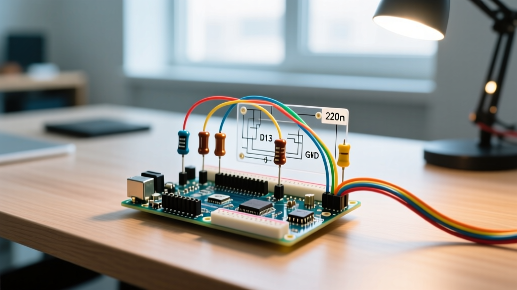
Expert Insight: Relying on active-low logic (where pressing a button pulls the pin to GND) forces your firmware to invert every state check. Migrating to an explicit external arduino pull-down resistor architecture allows for active-high logic, deterministic boot states, and vastly superior noise immunity.
Core Benefits of Migrating to an Arduino Pull-Down Resistor Network
Transitioning your schematic to use external pull-down resistors fundamentally changes the electrical characteristics of your input stage. Here is a comparison of the two architectures to highlight why production-grade designs favor external pull-downs for critical inputs.
| Feature | Internal Pull-Up (Prototype) | External Pull-Down (Production) |
|---|---|---|
| Impedance | High (20kΩ - 50kΩ) | Low & Precise (e.g., 4.7kΩ - 10kΩ) |
| Logic State | Active-Low (Inverted in code) | Active-High (Intuitive code mapping) |
| Noise Immunity | Poor (Susceptible to EMI) | Excellent (Strong low-impedance ground path) |
| Boot Determinism | Variable (Depends on MCU initialization) | Guaranteed (Hardware-tied to GND) |
| BOM Cost (2026) | $0.00 (Integrated) | ~$0.002 per channel (0402 SMD resistor) |
For a comprehensive overview of how digital pins handle internal versus external biasing, the Arduino Digital Pins Documentation provides excellent foundational context on why external biasing is preferred for long cable runs.
Calculating the Optimal Arduino Pull-Down Resistor Value
Unlike pull-up resistors, which must balance current draw against noise immunity, a pull-down resistor's primary job is to sink parasitic capacitance and provide a stiff ground reference. According to SparkFun's guide on biasing resistors, the value you choose dictates both the rise/fall times of your signal and the current wasted when the switch is closed.
Use the following data table to select the correct resistor value based on your specific migration scenario:
| Resistor Value | Current Draw (at 5V) | Best Use Case | Limitations |
|---|---|---|---|
| 4.7kΩ | 1.06 mA | Long wire runs, high-EMI industrial environments, mechanical relays. | Higher power consumption; not ideal for battery-powered IoT. |
| 10kΩ | 0.50 mA | Standard PCB pushbuttons, rotary encoders, general-purpose GPIO. | Standard choice; balances power and noise immunity perfectly. |
| 47kΩ | 0.10 mA | Battery-operated sensors, low-power sleep modes. | Increased susceptibility to high-frequency noise. |
| 100kΩ | 0.05 mA | Ultra-low-power wearables, energy harvesting circuits. | Very slow rise times; requires Schmitt trigger inputs to clean edges. |
Signal Conditioning: Adding Schmitt Triggers to the Migration
When you migrate to a high-value pull-down resistor (e.g., 47kΩ or 100kΩ) to save battery life, you introduce a new problem: parasitic capacitance. The PCB traces, the MCU pin capacitance, and the cable capacitance form an RC low-pass filter with your pull-down resistor. This results in a slow, sloping voltage rise when the switch is pressed, which can cause the ATmega328P to read multiple false triggers as the voltage slowly crosses the logic threshold.
The Upgrade Solution: Insert a hex inverting Schmitt trigger IC, such as the Nexperia 74HC14, between the switch node and the Arduino GPIO pin. The Schmitt trigger features built-in hysteresis—meaning it has separate, distinct voltage thresholds for turning ON and OFF. This cleanly squares off the slow, noisy analog slope into a sharp, deterministic digital edge, completely eliminating switch bounce and phantom triggers without requiring complex software debouncing routines.
PCB Layout Rules for Pull-Down Migration
Upgrading your schematic is only half the battle; the physical PCB layout dictates whether your new architecture will actually reject noise. Follow these strict layout rules when routing your external pull-down networks in 2026 EDA tools like KiCad 8 or Altium:
- Proximity to MCU: Place the pull-down resistor as close to the microcontroller pin as physically possible. The trace from the switch to the resistor pad can be long, but the trace from the resistor junction to the MCU pin must be under 5mm.
- Direct Ground Vias: Do not route the ground side of the pull-down resistor through long, winding traces to a ground plane. Place a 0.3mm via directly adjacent to the resistor's ground pad to inject the noise current straight into the internal ground plane.
- Guard Rings: If your pull-down network is located near high-frequency switching nodes (like a buck converter or motor driver), route a grounded copper guard ring around the pull-down junction to shield it from capacitive coupling.
- Component Footprints: For modern production runs, utilize 0402 or even 0201 imperial footprints. In 2026, automated SMT assembly lines handle 0201 resistors effortlessly, and they cost fractions of a penny, allowing you to add robust pull-downs to every spare GPIO pin without increasing board real estate.
Real-World Upgrade Case Study: Industrial Limit Switch Matrix
Consider a recent migration project involving a CNC router limit switch array. The original prototype used 6 microswitches wired to an Arduino Mega, relying entirely on INPUT_PULLUP. The switches were mounted on the machine chassis, requiring 3-meter cable runs back to the controller.
The Failure Mode: Whenever the spindle motor (a 2.2kW VFD-driven brushless motor) engaged, the high-frequency EMI coupled into the unshielded 3-meter cables. Because the internal pull-ups were ~30kΩ, the induced voltage spikes easily overcame the weak biasing, causing the CNC firmware to register false limit-switch hits and halt the machining process.
The Hardware Upgrade: The engineering team migrated the custom PCB to an active-high architecture. They installed 4.7kΩ external pull-down resistors at the MCU input stage, and added a 74HC14 Schmitt trigger buffer. The switches now sourced 5V through the long cables, while the local PCB side was held firmly to ground via the low-impedance 4.7kΩ path.
The Result: The 4.7kΩ resistor required a massive amount of induced EMI current to shift the voltage logic state, effectively rendering the 3-meter cables immune to the VFD noise. The total BOM cost increased by exactly $0.012 per channel (for the 0402 resistor and a fraction of the 74HC14 IC). This micro-investment in an external arduino pull-down resistor network eliminated weeks of software debouncing attempts and prevented thousands of dollars in scrapped machining material.
Summary
Migrating from internal pull-ups to an external pull-down architecture is a hallmark of transitioning from a hobbyist prototype to a professional, production-ready electronic product. By calculating the correct impedance, leveraging Schmitt triggers for signal conditioning, and adhering to strict PCB layout guidelines, you ensure that your microcontroller inputs remain deterministic, noise-free, and highly reliable in the real world.