
The Logic Level and Current Bottleneck
When integrating arduino motors into a robotics or automation project, the most common point of failure is not the code—it is the hardware compatibility mismatch between the microcontroller's logic levels, the motor driver's input thresholds, and the physical current demands of the load. Attempting to drive even a small 6V DC motor directly from an Arduino GPIO pin will instantly destroy the ATmega328P's internal silicon due to overcurrent. In 2026, with the maker market saturated with 3.3V and 5V hybrid boards, understanding the exact electrical boundaries of your microcontroller is mandatory for reliable motor control.
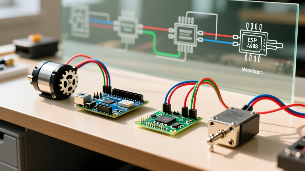
This compatibility guide breaks down the exact pairings for brushed DC, stepper, and servo motors, detailing the specific driver ICs, voltage drops, and logic-level traps you must navigate.
Microcontroller Logic & Current Matrix
Before selecting a motor driver, you must understand your board's GPIO limits. Supplying a motor driver's logic pins (DIR, STEP, PWM) requires minimal current, but the voltage level must meet the driver's VIH (High-level input voltage) threshold.
| Microcontroller Board | Core Logic Level | I/O Voltage Tolerance | Max Current per I/O Pin | Motor Driver Compatibility Notes |
|---|---|---|---|---|
| Arduino Uno R3 / Mega 2560 | 5V | 5.5V Absolute Max | 20mA (Recommended) | Native compatibility with almost all 5V optocoupler and logic drivers. |
| Arduino Uno R4 Minima | 3.3V (RA4M1 Core) | 5V Tolerant I/O | 8mA per pin | Can read 5V signals, but outputs 3.3V. May fail to trigger 5V-only optocouplers. |
| Arduino Nano 33 IoT | 3.3V | 3.6V Absolute Max | 7mA per pin | Strictly 3.3V. Requires logic level shifters for 5V drivers. Will fry if exposed to 5V. |
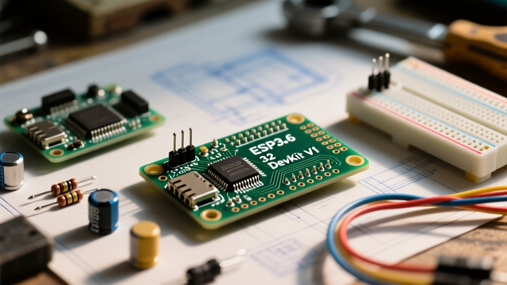
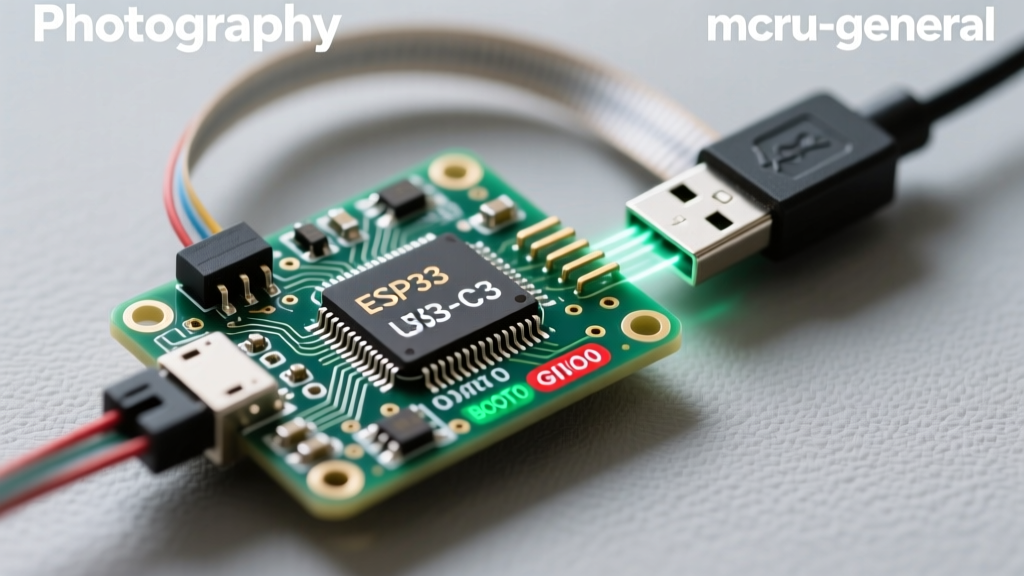
| ESP32-WROOM-32 | 3.3V | 3.6V Absolute Max | 12mA (varies by pin) | Excellent PWM capabilities, but requires 3.3V-native drivers or level shifters. |
Brushed DC Motors: BJT vs. MOSFET Drivers
Brushed DC motors are ubiquitous in DIY rovers and conveyor builds. The compatibility choice here revolves around efficiency and voltage drop. The motor's stall current dictates your driver selection.
The L298N Voltage Drop Trap
The L298N is the most recognized arduino motors driver, often bundled in starter kits for $4 to $8. However, it uses bipolar junction transistor (BJT) H-bridge topology. According to the STMicroelectronics datasheet, the L298N suffers from a combined saturation voltage drop (VCE(sat)) of up to 3.2V at 2A. If you power a 6V motor through an L298N using a 7.2V battery pack, the motor only receives roughly 4V, resulting in a massive 60% loss in available torque and severe thermal throttling of the driver IC.
The Modern Standard: TB6612FNG and DRV8871
For modern builds, MOSFET-based drivers are mandatory for efficiency.
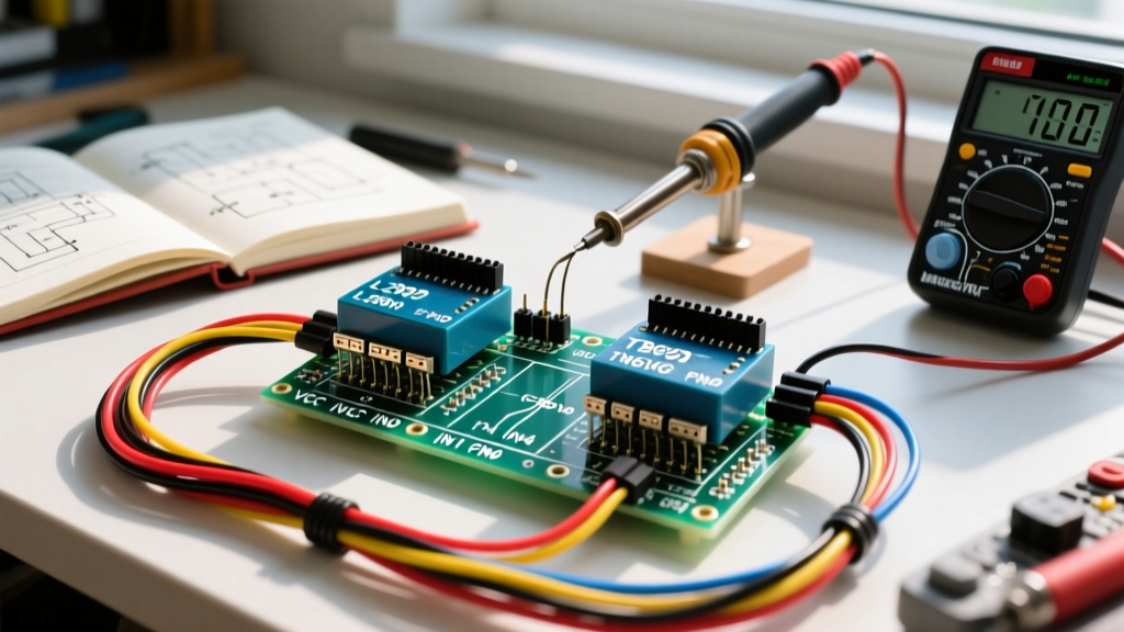
- TB6612FNG: Handles up to 1.2A continuous per channel (3.2A peak) with a negligible 0.5V drop. Ideal for 6V-12V micro metal gearmotors (like Pololu's N20 series). Priced around $6 to $10.
- TI DRV8871: A single-channel brushed DC driver capable of 3.6A continuous. It requires only two PWM-capable GPIO pins from your Arduino, eliminating the need for complex logic enable pins. Priced at $4 to $6, it is the superior choice for high-torque 12V wheelchair motors or automotive wiper motors.
Stepper Motors (NEMA 17 & 23): Microstepping and Thermal Limits
Stepper motors, particularly the NEMA 17 (e.g., the 17HS4401 rated at 1.7A), are the backbone of CNC routers and 3D printers. Compatibility here is defined by the driver IC's ability to handle inductive kickback and manage coil current via decay modes.
Driver IC Comparison Matrix
| Driver IC | Max Continuous Current | Microstepping | Control Interface | Best Use Case |
|---|---|---|---|---|
| Allegro A4988 | 1.0A (w/o cooling) | 1/16 | STEP / DIR | Low-load NEMA 17 prototyping, basic plotters. |
| TI DRV8825 | 1.5A (w/o cooling) | 1/32 | STEP / DIR | Standard 3D printer extruders and X/Y gantries. |
| Trinamic TMC2209 | 2.0A (RMS) | 1/256 (interpolated) | STEP / DIR / UART | Silent operation, sensorless homing (StallGuard). |
| Toshiba TB6600 | 4.0A (Peak) | 1/32 | Optocoupler STEP/DIR | NEMA 23 motors, heavy-duty CNC router axes. |
Information Gain: Calculating VREF for Current Limiting
A critical failure mode when pairing a DRV8825 with a NEMA 17 motor is improper current limiting, which leads to skipped steps or fried coils. You must manually tune the VREF potentiometer on the driver breakout. The formula for the Texas Instruments DRV8825 is:
Current Limit = VREF × 2 (Therefore, VREF = Current Limit / 2)
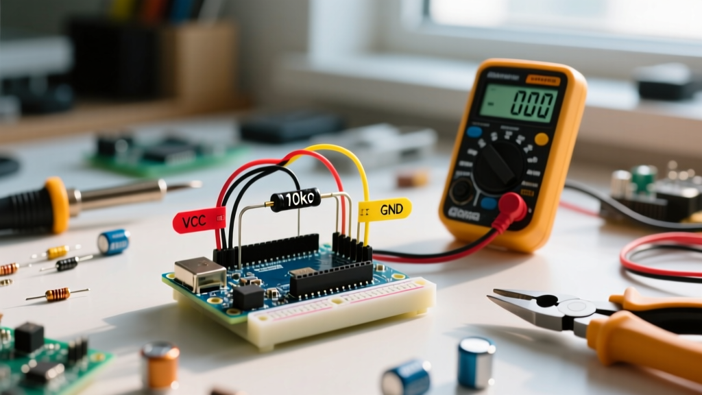
If your NEMA 17 motor is rated for 1.7A per phase, your target VREF is 0.85V. Using a digital multimeter, place the positive probe on the VREF test pad and the negative probe on the driver's ground. Adjust the brass potentiometer until you hit exactly 0.85V. Crucial Edge Case: Always ensure a 100µF electrolytic capacitor is soldered across the VMOT and GND pins on the breakout board. Inductive voltage spikes from the stepper coils can easily exceed the DRV8825's 45V absolute maximum rating, destroying the IC instantly if decoupling is absent.
The 3.3V Logic Trap: ESP32 and Nano 33 IoT with Optocouplers
As makers migrate to 3.3V ecosystems like the ESP32 and Arduino Nano 33 IoT for Wi-Fi and BLE capabilities, a massive compatibility issue arises with industrial-style stepper drivers like the TB6600. These drivers use internal PC817 optocouplers to isolate the high-voltage motor power from the low-voltage logic.
The internal infrared LED of the optocoupler requires a forward voltage (Vf) of roughly 1.2V and a minimum forward current of 8mA to reliably trigger the phototransistor. Most TB6600 boards include a 220Ω current-limiting resistor on the input. If you supply 5V from an Uno R3, the current is roughly 17mA—perfect. If you supply 3.3V from an ESP32, the current drops to around 4mA. The optocoupler will fail to switch, resulting in dead motors or erratic microstepping.
Hardware Solutions for 3.3V MCUs
- Logic Level Shifter: Use a TXS0108E bi-directional level shifter between your ESP32/Nano 33 IoT and the TB6600 inputs. ($2-$4 per module).
- Native 3.3V Drivers: Bypass optocoupled drivers entirely and use Trinamic TMC2209 or TI DRV8825 modules, which natively accept 3.3V logic highs on their STEP and DIR pins.
- The Pull-Up Resistor Hack: Wire the optocoupler cathode (e.g., PUL-) directly to the ESP32's 3.3V GPIO pin, and connect the anode (PUL+) to a 5V source through a 150Ω resistor. When the ESP32 pin pulls LOW to 0V, it completes the 5V circuit, forward-biasing the LED safely.
Servos and BLDCs: PWM Limits and BEC Integration
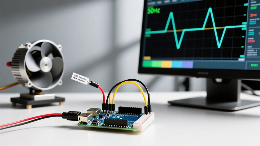
Standard hobby servos (like the SG90) and high-torque metal-gear servos (like the MG996R) are controlled via standard 50Hz PWM signals. While an Arduino Uno can generate this signal easily, the power delivery is where compatibility breaks down.
An SG90 micro servo draws roughly 700mA at stall. An MG996R can spike to 2.5A at stall under load. The Arduino's onboard 5V linear regulator (typically an NCP1117 or similar) is rated for 800mA to 1A maximum, and that is shared with the ATmega328P and any onboard LEDs. Connecting even two MG996R servos to the Arduino's 5V rail will cause the regulator to thermally shutdown or melt, resetting your MCU continuously.
The BEC Requirement
For any servo setup exceeding one standard micro servo, you must use an external Battery Eliminator Circuit (BEC). A switching UBEC (Universal BEC) rated for 5V/5A costs around $8 to $12. You wire the UBEC's input to your main LiPo battery (e.g., 2S or 3S), and route the 5V output directly to a servo power rail breadboard. Crucial Step: You must tie the BEC's ground wire to the Arduino's GND pin to establish a common ground reference; otherwise, the PWM signal from the Arduino will be unreadable by the servo's internal controller.
Summary Checklist for Motor Integration
- Verify Logic Levels: Check if your driver requires 5V to trigger optocouplers or accepts 3.3V natively.
- Calculate Stall Current: Size your motor driver and power supply to handle 150% of the motor's rated stall current.
- Decouple Inductive Loads: Always use flyback diodes for brushed DC motors and bulk capacitors for stepper drivers.
- Isolate Power Rails: Never route motor coil current through the Arduino's onboard 5V/3.3V regulators.
By respecting the electrical boundaries outlined in this matrix and leveraging modern MOSFET and chopper-based drivers, you can build arduino motors systems that deliver industrial-grade reliability without frying your microcontroller. For further reading on stepper driver decay modes and thermal management, consult the engineering guides at Pololu Robotics and the official Arduino Hardware Documentation.