
Beyond the Potentiometer: Understanding Incremental Encoders
When designing human-machine interfaces (HMIs) for microcontrollers, makers frequently hit the physical limitations of standard potentiometers. Potentiometers are bound by a fixed rotational sweep (usually 270 degrees) and suffer from analog-to-digital converter (ADC) noise, mechanical wear, and wiper degradation over time. The solution for infinite-rotation, noise-immune input is the incremental rotary encoder. However, successfully integrating a rotary encoder with Arduino hardware requires a fundamental understanding of quadrature signals, contact bounce physics, and interrupt-driven software architecture. In this guide, we will dissect the electromechanical theory, wiring topologies, and edge-case failure modes of rotary encoders in modern maker projects.
The Core Concept: Quadrature Encoding and Phase Shifts
Unlike absolute encoders which output a unique digital word for every angular position (often using Gray code over 8 to 14 parallel pins), incremental encoders output a continuous stream of pulses. The most common variant used in DIY electronics is the mechanical quadrature encoder. Inside the housing, a rotating slotted disk or a patterned contact ring passes over two sets of stationary wipers, creating two distinct square-wave signals: Phase A (often labeled CLK) and Phase B (often labeled DT).
The critical concept here is the 90-degree electrical phase shift between Channel A and Channel B. This offset is what allows the microcontroller to determine not just that the knob is turning, but which direction it is turning. By monitoring the state of Channel B at the exact moment Channel A transitions from HIGH to LOW (or LOW to HIGH), the microcontroller can decode the direction of rotation.
Decoding the State Machine
To visualize this, consider the four possible binary states of the A and B channels. As the shaft rotates through one mechanical detent, the encoder cycles through a specific sequence of these states. If it cycles forward, you increment your position counter; if it cycles backward, you decrement it.
| State Number | Phase A (CLK) | Phase B (DT) | Transition Direction (Clockwise) |
|---|---|---|---|
| 1 | HIGH | HIGH | Start of cycle |
| 2 | LOW | HIGH | A falls while B is HIGH |
| 3 | LOW | LOW | B falls while A is LOW |
| 4 | HIGH | LOW | A rises while B is LOW |
If the sequence reverses (e.g., State 1 to 4 to 3), the microcontroller registers counter-clockwise rotation. This elegant hardware design eliminates the need for complex directional sensing algorithms, offloading the physics to the mechanical geometry of the encoder itself.
Hardware Deep Dive: Choosing the Right Encoder Module
As of 2026, the market is flooded with encoder modules ranging from sub-dollar imports to precision industrial components. Selecting the wrong hardware is the primary reason makers experience 'jittery' or missed inputs. Below is a comparison of the three most common tiers of encoders used with Arduinos.
| Component / Module | Typical Cost | Pulses Per Rev (PPR) | Mechanical Detents | Contact Bounce Time | Best Use Case |
|---|---|---|---|---|---|
| KY-040 Breakout | $1.00 - $1.50 | 20 PPR | 20 Detents | 5ms - 15ms (High) | Basic UI menus, low-speed volume knobs |
| Bourns PEC12R-4215F (Bare) | $3.20 - $4.50 | 24 PPR | 24 Detents | < 2ms (Low) | Precision instruments, audio equipment, robotics |
| SparkFun RGB Encoder (COM-15228) | $14.95 | 24 PPR | 24 Detents | < 2ms | Advanced HMIs requiring visual feedback |
Expert Insight: The ubiquitous KY-040 module is notorious for severe contact bounce and weak detent springs. While acceptable for prototyping, its internal wipers oxidize quickly, leading to open circuits within a year of heavy use. For permanent installations, bare Bourns PEC12R or PEC11R series encoders are the industry standard. They feature robust carbon-composition contacts and precise mechanical detents that provide superior tactile feedback and vastly cleaner electrical signals.
Electrical Wiring and Hardware Debouncing
A common beginner mistake is wiring the encoder's CLK and DT pins directly to the Arduino and relying solely on the microcontroller's internal pull-up resistors. While the INPUT_PULLUP mode activates an internal resistor (typically 20kΩ to 50kΩ on an ATmega328P), this high impedance makes the lines highly susceptible to electromagnetic interference (EMI) and extends the RC time constant of the parasitic capacitance, worsening signal ringing.
The Optimal Wiring Topology
- External Pull-ups: Wire 10kΩ resistors from both the CLK and DT lines to your logic voltage (usually 5V or 3.3V). This provides a stiff, low-impedance HIGH state.
- Common Ground: Connect the encoder's common (C) pin to the Arduino GND. If using a module with a pushbutton (SW), ensure the button's ground is shared with the encoder ground to prevent ground loops.
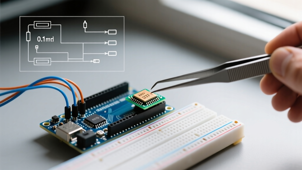
- Hardware Debouncing (RC Filter): Mechanical wipers physically bounce when they make contact, creating high-frequency noise spikes that can trigger false interrupts. To eliminate this in hardware, place a 0.1µF ceramic capacitor between each signal line (CLK and DT) and GND.
Engineering Math: With a 10kΩ pull-up resistor and a 0.1µF capacitor, the RC time constant (τ = R × C) is 1 millisecond. This means the signal will smoothly transition over ~1ms, effectively filtering out the microsecond-scale contact bounce spikes without introducing enough latency to miss a step at normal human rotation speeds.
Software Architecture: Why Polling Fails and Interrupts Succeed
Reading a rotary encoder using digitalRead() inside the main loop() is a recipe for disaster. If your main loop takes 10 milliseconds to execute (perhaps due to updating an I2C OLED display or reading a slow sensor), and the user flicks the encoder quickly, the microcontroller will completely miss the state transitions between polls. This results in the infamous 'two steps forward, one step back' jitter, or total unresponsiveness.
The correct approach is to utilize hardware interrupts. By attaching the encoder pins to the microcontroller's interrupt vectors, the CPU immediately pauses its current task, executes an Interrupt Service Routine (ISR) to decode the state, and resumes. According to the official Arduino attachInterrupt() documentation, the ATmega328P (Arduino Uno/Nano) has dedicated hardware interrupts only on pins 2 and 3 (INT0 and INT1).
Handling the Pushbutton and Secondary Axes
What if you need to read the encoder's integrated pushbutton, or you are using an Arduino Mega with multiple encoders? You must leverage Pin Change Interrupts (PCINT). Unlike dedicated hardware interrupts that trigger only on specific edges (RISING/FALLING), PCINTs trigger on any logic change on a specific port register. Libraries like Paul Stoffregen's renowned Encoder library abstract this complexity, automatically mapping pins to their respective PCINT vectors and managing the state-machine logic in the background.
Critical Edge Cases and Failure Modes
Even with perfect wiring and interrupt-driven code, advanced makers must navigate several edge cases inherent to quadrature decoding:
- ISR Blocking and I2C Collisions: Never use
Wire.requestFrom()orSerial.print()inside an ISR. I2C communication relies on its own interrupts; blocking the CPU inside an encoder ISR will cause the I2C bus to hang, freezing your entire sketch. Keep your ISR under 5 microseconds by simply updating avolatileinteger counter, and handle the UI updates in the main loop. - The 'Mid-Detent' Resting State: Some cheap encoders rest in an unstable state where one channel is transitioning while the other is stable. If your code only triggers on the FALLING edge of Channel A, you might miss half the detents. Always configure your interrupts to trigger on
CHANGEand evaluate the full 2-bit state matrix. - Velocity Scaling: In audio or UI applications, users expect 'scroll acceleration'—turning the knob slowly moves the value by 1, but flicking it quickly moves it by 10. This cannot be done in the ISR. Instead, calculate the delta between the current encoder count and the previous count in the main loop, apply a non-linear mapping function based on the time delta, and then reset the tracking variable.
Summary: Building a Robust HMI
Integrating a rotary encoder with an Arduino is a masterclass in bridging mechanical physics with digital logic. By abandoning cheap, high-bounce modules in favor of quality components like the Bourns PEC12R, implementing proper 10kΩ/0.1µF hardware debouncing, and utilizing hardware interrupts for state tracking, you transform a frustrating, jittery input device into a precision instrument. For further reading on encoder implementations and advanced HID applications, the Adafruit Rotary Encoder Guide and SparkFun's Hookup Tutorial provide excellent supplementary schematics and library examples.