
Understanding the Arduino pulseIn() Function
The pulseIn() function is a core timing utility in the Arduino framework, designed to measure the duration of a specific logic state (HIGH or LOW) on a digital pin. When called, the function waits for the pin to transition to the target state, starts an internal hardware timer, and stops counting when the pin transitions back. It returns the pulse length in microseconds as an unsigned long data type.
While seemingly simple, mastering pulseIn() requires a deep understanding of its blocking nature, timeout parameters, and hardware limitations. In this guide, we will explore two of the most common real-world applications for this function: decoding RC receiver PWM signals and measuring distance with HC-SR04 ultrasonic sensors. We will also cover advanced workarounds for the function's inherent bottlenecks.
Core Syntax:
unsigned long duration = pulseIn(pin, value, timeout);
Thetimeoutparameter is optional but highly recommended. By default, it is set to 1 second (1,000,000 microseconds). If no pulse arrives, the function blocks your entire sketch for a full second unless you specify a shorter timeout, such as 25000 (25 milliseconds).
Real-World Application 1: Decoding RC Receiver PWM Signals
Hobbyist radio control (RC) systems, such as the popular FlySky FS-iA6B 6-channel receiver (typically priced around $15 to $18 in 2026), communicate with servos and flight controllers using standard PWM (Pulse Width Modulation) signals. These signals operate at a 50Hz frame rate, meaning a new pulse is sent every 20 milliseconds (20,000 µs). The pulse width itself varies between 1000 µs and 2000 µs, representing the physical position of the transmitter's control sticks.
Wiring the FS-iA6B Receiver
To interface the receiver with an Arduino Nano or Uno R3, connect the receiver's power and signal pins as follows:
- VCC: Connect to the Arduino 5V pin (The FS-iA6B requires 4.0V - 6.5V).
- GND: Connect to Arduino GND.
- Signal (Channel 1): Connect to Arduino Digital Pin 2.
The Standard pulseIn() Sketch for RC Decoding
Below is the optimized code to read a single RC channel. Notice the explicit timeout value of 25000. Because the RC signal repeats every 20ms, a 25ms timeout guarantees the function will reset and try again without locking up the microcontroller for a full second if the receiver loses signal.
const int rcPin = 2;
unsigned long rcValue;

void setup() {
  Serial.begin(115200);
  pinMode(rcPin, INPUT);
}

void loop() {
  // Wait for a HIGH pulse, timeout after 25,000 microseconds (25ms)
  rcValue = pulseIn(rcPin, HIGH, 25000);

  // Constrain the value to standard RC limits to filter noise
  rcValue = constrain(rcValue, 1000, 2000);

  Serial.print("RC Channel 1: ");
  Serial.println(rcValue);
  delay(20); // Align roughly with the 50Hz RC frame rate
}
The Blocking Problem: Why Your Sketch Stutters
The most critical edge case of pulseIn() is that it is a blocking function. While it is waiting for a pulse to begin or end, the Arduino CPU cannot execute any other code. It cannot update displays, read I2C sensors, or process serial data.
If you attempt to read six RC channels sequentially using six consecutive pulseIn() calls, your sketch will suffer from severe latency. Because the pulses on different channels are staggered sequentially within that 20ms window, the microcontroller will spend the vast majority of its time waiting for the next pulse to arrive. For multi-channel RC decoding or high-speed robotics, relying solely on sequential pulseIn() calls is a fundamental architectural flaw. Later in this guide, we will discuss Pin Change Interrupts (PCINT) as the professional alternative.
Real-World Application 2: High-Precision HC-SR04 Ultrasonic Measurement
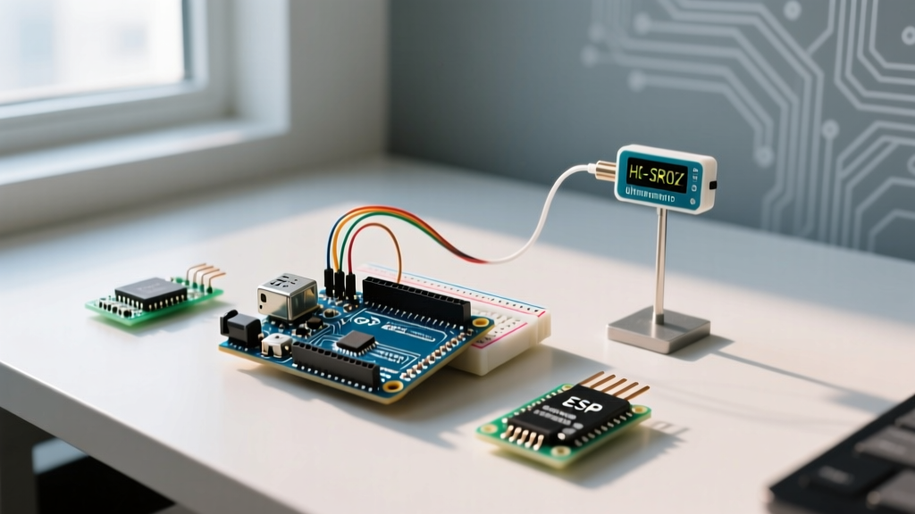
The HC-SR04 ultrasonic sensor remains a staple in maker projects, costing roughly $2.50 to $4.00 per unit. It measures distance by emitting a 40kHz acoustic burst and timing how long it takes for the echo to return. The Echo pin outputs a HIGH pulse whose duration is directly proportional to the distance of the object.
Triggering and Reading the Echo
To use pulseIn() with the HC-SR04, you must first send a precise 10-microsecond HIGH pulse to the Trigger pin to initiate the acoustic burst. Then, you use pulseIn() to measure the resulting HIGH pulse on the Echo pin.
const int trigPin = 9;
const int echoPin = 10;

void setup() {
  Serial.begin(115200);
  pinMode(trigPin, OUTPUT);
  pinMode(echoPin, INPUT);
}

void loop() {
  digitalWrite(trigPin, LOW);
  delayMicroseconds(2);
  digitalWrite(trigPin, HIGH);
  delayMicroseconds(10);
  digitalWrite(trigPin, LOW);

  // Read the echo pulse, timeout at 30ms (max range ~5 meters)
  unsigned long duration = pulseIn(echoPin, HIGH, 30000);

  // Calculate distance assuming standard room temperature (20C)
  float distance = (duration * 0.0343) / 2.0;

  if (duration == 0) {
    Serial.println("Out of range or timeout");
  } else {
    Serial.print("Distance: ");
    Serial.print(distance);
    Serial.println(" cm");
  }
  delay(60); // HC-SR04 requires ~60ms between readings to avoid acoustic cross-talk
}
Temperature Compensation Matrix
A common mistake in ultrasonic measurement is assuming the speed of sound is a static constant. The speed of sound in dry air varies with temperature. If your project operates in an unheated garage in winter or a hot greenhouse in summer, your pulseIn() distance calculations will drift significantly. According to standard acoustic physics, the speed of sound increases by approximately 0.606 m/s for every 1°C rise in temperature.
| Ambient Temperature (°C) | Speed of Sound (m/s) | Divisor Constant for 1-Way (cm/µs) | Measurement Error at 100cm (vs 20°C baseline) |
|---|---|---|---|
| 0°C (Freezing) | 331.3 | 0.0331 | -3.5 cm |
| 10°C (Cold Garage) | 337.4 | 0.0337 | -1.7 cm |
| 20°C (Room Temp) | 343.4 | 0.0343 | Baseline (0 cm) |
| 30°C (Warm Summer) | 349.5 | 0.0349 | +1.8 cm |
| 40°C (Hot Enclosure) | 355.5 | 0.0355 | +3.6 cm |
For high-precision industrial applications in 2026, engineers typically pair the HC-SR04 with a DS18B20 digital temperature sensor to dynamically adjust the multiplier constant in real-time based on the table above.
Advanced Workaround: pulseInLong() and Pin Change Interrupts
As of recent Arduino core updates, the Arduino pulseInLong() Reference provides a superior alternative when your sketch utilizes hardware interrupts. Standard pulseIn() can yield inaccurate readings if an Interrupt Service Routine (ISR) fires during the pulse measurement, because the hardware timer pauses while the ISR executes. pulseInLong() accounts for these pauses, providing highly accurate timing even in interrupt-heavy environments, such as those using rotary encoders or software serial libraries.
However, if you are building a multi-rotor flight controller or a complex RC rover, neither pulseIn() nor pulseInLong() is sufficient due to the blocking issue. The industry-standard approach is to abandon polling entirely and use Pin Change Interrupts (PCINT). By attaching an ISR to the RC input pins, the microcontroller records the micros() timestamp precisely when the pin rises and falls, calculating the pulse width in the background without halting the main loop(). When using ISRs to store these timestamps, you must declare your timing variables with the volatile keyword to prevent the compiler from optimizing them out of memory.
Troubleshooting Common pulseIn() Failures
When your pulseIn() implementation behaves erratically, consult this diagnostic checklist:
- Function Always Returns 0: This indicates a timeout. Verify your wiring, ensure the sensor is receiving adequate current (the HC-SR04 can draw up to 15mA during the acoustic burst, which may brownout a weak USB power supply), and confirm that your timeout parameter is longer than the expected maximum pulse width.
- Severe Jitter in RC Readings: RC receivers output a continuous stream of pulses. If your main loop has a
delay()longer than 20ms, you might be measuring the tail-end of one pulse and the beginning of the next. Remove blocking delays and rely on non-blockingmillis()timers for your main loop logic. - Ultrasonic Cross-Talk: If using multiple HC-SR04 sensors in the same physical space, firing them simultaneously will cause acoustic cross-talk, leading to wildly incorrect
pulseIn()durations. You must fire them sequentially with a minimum 60ms acoustic settling delay between each sensor trigger. - 5V vs 3.3V Logic Mismatch: If you are using a 3.3V microcontroller (like an ESP32 or Arduino Due) to read a 5V RC receiver signal, the
pulseIn()function may fail to register the HIGH state reliably, or you risk damaging the GPIO pin. Always use a bidirectional logic level converter or a simple resistor voltage divider (e.g., 10kΩ and 15kΩ) to step the 5V PWM signal down to a safe 3.0V.
By understanding the mechanical limitations of the pulseIn() function and applying the appropriate hardware and software compensations, you can achieve reliable, microsecond-accurate measurements in even the most demanding embedded systems.