
The Ultimate Quick Reference for Arduino GPS Integration
Integrating location tracking into your microcontroller projects is a rite of passage for any maker. When navigating global supply chains or browsing international electronics marketplaces, you will frequently encounter the term modul gps arduino. Whether you are importing a generic, unbranded breakout board or utilizing a premium, domestically sourced shield, the underlying physics of satellite triangulation and NMEA 0183 data parsing remain identical.
This FAQ and quick reference guide bypasses the fluff, delivering exact wiring schematics, library comparisons, and edge-case troubleshooting for GPS integration on ATmega328P (Uno/Nano) and ESP32 architectures in 2026.
Module Selection Matrix (2026 Market Snapshot)
Choosing the right receiver depends on your TTFF (Time to First Fix) requirements, power budget, and environmental constraints. Below is a comparison of the most prevalent modules used in the maker community today.
| Module / Chipset | Channels | Approx. Price (2026) | Best Use Case |
|---|---|---|---|
| NEO-6M (Generic) | 50 | $10 - $14 | Basic logging, student projects, high-altitude balloons. |
| NEO-M8N (u-blox) | 72 | $22 - $28 | Drones, automotive tracking, concurrent GNSS (GPS+GLONASS). |
| SAM-M10Q (u-blox) | 96 | $35 - $42 | Ultra-low power wearables, IoT edge devices requiring Galileo/BeiDou. |
| PA1010D (MTK) | 66 | $18 - $24 | Breadboard-friendly prototyping, indoor debugging (high sensitivity). |
Source: For detailed architectural differences between receiver generations, refer to the u-blox NEO-M8 series documentation.
Hardware & Wiring FAQ
Q: How do I wire a 3.3V GPS module to a 5V Arduino Uno without frying it?
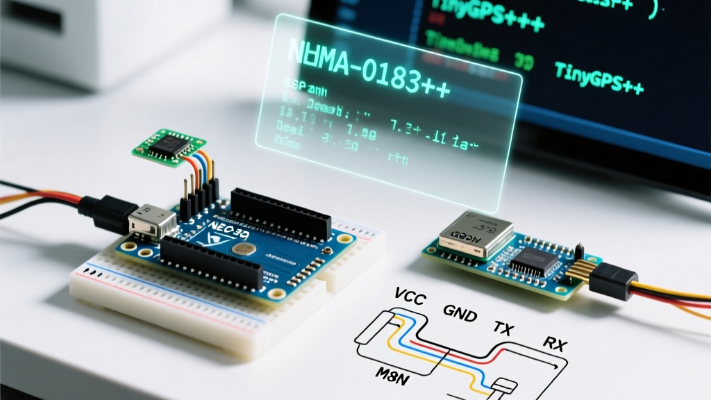
Most generic NEO-6M and NEO-M8N breakout boards feature an onboard 3.3V LDO (Low Dropout Regulator) like the AMS1117. This means you can safely connect the VCC pin to the Arduino's 5V pin. However, the data pins operate at 3.3V logic.
- GPS TX to Arduino RX: The GPS transmits at 3.3V. The ATmega328P recognizes anything above 2.0V as a logical HIGH. You can connect this directly without a level shifter.
- Arduino TX to GPS RX: The Arduino transmits at 5V. Feeding 5V into a 3.3V GPS RX pin can degrade or destroy the module's UART transceiver over time. You must use a voltage divider.
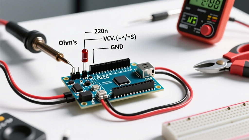
Pro-Tip Voltage Divider: Solder a 1kΩ resistor in series with the Arduino TX line, and a 2kΩ resistor from the GPS RX pin to GND. This drops the 5V signal to a safe ~3.3V.
Q: Which pins should I use on an ESP32?
Never use SoftwareSerial on an ESP32 if you can avoid it; the dual-core architecture handles hardware UARTs natively, and software emulation causes severe RTOS interrupt conflicts.
- Use HardwareSerial(2) (UART2).
- Connect GPS TX to GPIO 16 (ESP32 RX2).
- Connect GPS RX to GPIO 17 (ESP32 TX2).
- Initialize in code via
Serial2.begin(9600, SERIAL_8N1, 16, 17);
Software & NMEA Parsing FAQ
Q: TinyGPS++ vs. NMEAGPS — Which library should I use?
Parsing raw NMEA strings manually using String objects will quickly fragment your SRAM and crash an ATmega328P. You must use a dedicated parsing library.
- TinyGPS++: The undisputed king of ease-of-use. It uses an object-oriented approach (
gps.location.lat()). It consumes roughly 2,200 bytes of program memory and minimal RAM. Best for 90% of standard maker projects. - NMEAGPS: Highly optimized, interrupt-driven, and strictly typed. It is significantly faster and uses less RAM than TinyGPS++, but the learning curve is steep, and it requires modifying the library's configuration headers to select specific NMEA sentences. Best for high-speed (10Hz+) drone telemetry.
Q: Why is my Arduino running out of memory when reading GPS data?
By default, a GPS module broadcasts up to 8 different NMEA sentences (GGA, RMC, VTG, GSA, GSV, etc.) every second. This floods the Arduino's 64-byte serial buffer, causing dropped characters and memory bloat if you are storing strings.
The Fix: Configure your module to only output the sentences you actually need. For basic latitude, longitude, and time, you only need RMC and GGA. You can send UBX-CFG-MSG binary commands via the u-blox U-Center software to permanently disable the unused sentences, reducing serial traffic by 70%.
Q: What is the difference between $GPGGA and $GPRMC?
Understanding the NMEA 0183 standard is critical for debugging. Here is the quick breakdown:
- $GxGGA (Global Positioning System Fix Data): Provides the 3D fix. Includes latitude, longitude, fix quality (0=invalid, 1=GPS, 2=DGPS), number of satellites tracked, horizontal dilution of precision (HDOP), and altitude above mean sea level.
- $GxRMC (Recommended Minimum Specific GNSS Data): Provides the vital navigational data. Includes latitude, longitude, speed over ground, track angle (heading), and the current date and time.
Note: If you need altitude, you must parse GGA. If you need the real-time clock (RTC) date stamp, you must parse RMC. TinyGPS++ handles both seamlessly.
Troubleshooting & Edge Cases
Q: My GPS LED is blinking, but TinyGPS++ returns '0.000' for coordinates. Why?
A blinking LED (usually 1Hz) simply indicates the module has power and is outputting serial data. It does not mean it has a satellite fix. This is known as a Cold Start.
- Cold Start TTFF: If the module has no stored almanac or ephemeris data, it must blindly search the sky for Doppler-shifted signals. This takes 27 to 45 seconds outdoors, and can take up to 15 minutes if the sky view is partially obstructed.
- The VBAT Pin: To achieve a 'Hot Start' (TTFF under 2 seconds), the module's internal RTC and SRAM must remain powered when the main VCC is cut. Connect a 3V coin cell (e.g., CR1220) or a supercapacitor to the VBAT pin. If your breakout board lacks a battery holder, every power cycle forces a 30+ second cold start.
Q: The GPS works outside, but fails instantly when I bring it indoors for testing.
GPS signals operate at L1 band frequencies (~1.575 GHz) and are incredibly weak by the time they reach Earth's surface (around -130 dBm). Standard ceramic patch antennas cannot penetrate concrete, metal roofs, or low-E glass.
Indoor Testing Workaround: If you must test your parsing logic indoors, do not rely on live sky data. Instead, write a script that injects pre-recorded NMEA sentences into your Arduino's serial port via the IDE Serial Monitor. This isolates software bugs from hardware signal limitations.
Q: I'm using SoftwareSerial on an Uno, but the data is full of garbage characters.
SoftwareSerial relies on pin-change interrupts and precise CPU timing. If your sketch includes blocking code (like delay()), heavy LCD updates, or long Wire.h I2C transactions, the Arduino will miss the microsecond-level UART start bits, resulting in corrupted bytes.
Solutions:
- Eliminate all
delay()calls. Usemillis()based non-blocking state machines. - Reduce the GPS baud rate to 4800 bps using U-Center to give the software serial buffer more breathing room.
- Upgrade to an Arduino Mega (which has 4 hardware UARTs) or an ESP32.
Summary Checklist for Deployment
Before sealing your project in an enclosure, verify the following:
- [ ] Antenna Placement: The ceramic patch must face the sky directly. Ground planes (copper pour) beneath the antenna improve gain.
- [ ] Baud Rate Match: Ensure your
Serial.begin()matches the module (default is almost always 9600 bps for NEO-6M/M8N). - [ ] Logic Levels: 5V TX lines are stepped down to 3.3V via resistors.
- [ ] Backup Power: VBAT is supplied with 1.4V - 3.6V for hot-start capability.