
The Hidden Thermodynamics of the Barrel Jack
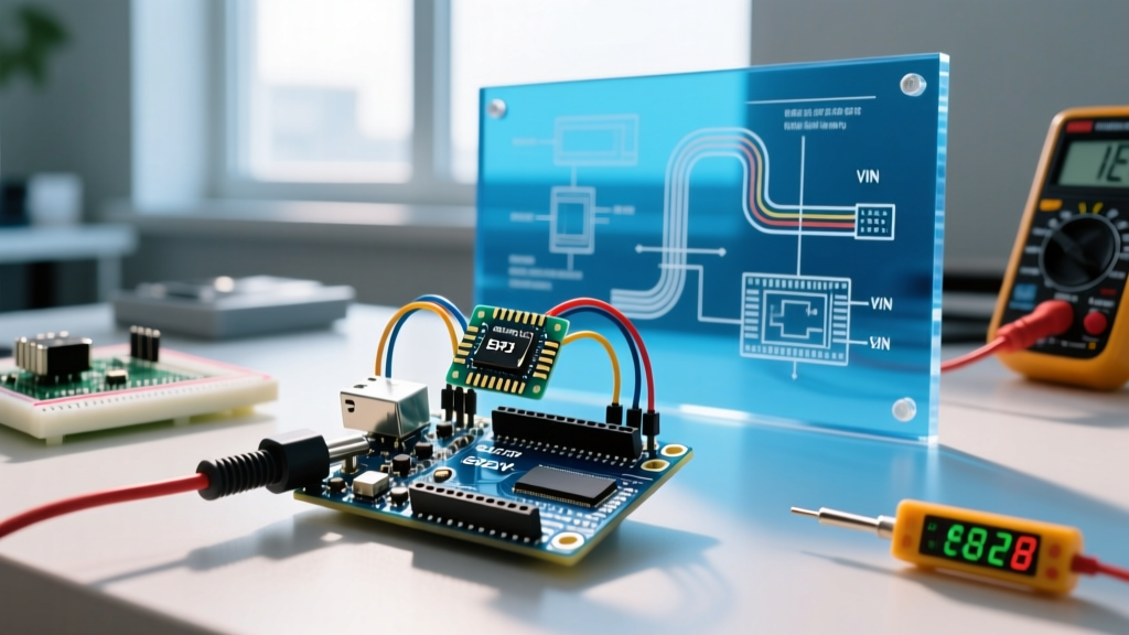
Powering an Arduino with a 12V adapter via the DC barrel jack or the VIN pin seems like the most straightforward way to run mobile robots, automotive relay modules, or NEMA 17 stepper motor projects. However, as of 2026, even with the advanced silicon found in the Arduino Uno R4 Minima and the Nano ESP32, the fundamental physics of onboard linear voltage regulators remain a massive bottleneck. When makers experience random microcontroller resets, erratic sensor readings, or a burning smell, the Arduino 12 volt power supply configuration is almost always the culprit.
The core issue is not the 12V power supply itself, but how the Arduino handles the voltage step-down. Unlike switching power supplies, the Arduino's onboard Low Dropout (LDO) regulator (typically an NCP1117 series in a SOT-223 package) operates by burning off excess voltage as heat. Understanding this thermodynamic reality is the first step in diagnosing power-related MCU failures.
Diagnostic Matrix: Symptom to Root Cause
Before grabbing a multimeter, match your project's erratic behavior to the diagnostic matrix below. This framework isolates whether the error stems from thermal limits, trace overcurrent, or ground loops.
| Observed Symptom | Diagnostic Measurement | Root Cause |
|---|---|---|
| MCU resets every 2–5 minutes under load | LDO case temp > 90°C (Touch test or thermal camera) | LDO Thermal Shutdown Protection |
| 5V pin outputs 3.2V or fluctuates wildly | Continuity test from barrel jack center pin to LDO input | Internal LDO silicon degradation / junction failure |
| USB disconnects from PC when 12V is plugged in | Voltage spike on 5V rail during plug-in event | Auto-reset circuit conflict or ground bounce |
| Project works on USB, but dies on 12V battery | Battery voltage drops below 6.5V under load | Battery C-rating too low / LDO dropout voltage reached |
Failure Mode 1: The Thermal Shutdown Reset Loop
The most common error diagnosis in 12V Arduino projects is the 'ghost reset.' Your sketch runs perfectly, then suddenly restarts without a watchdog timer or software trigger. This is the LDO's internal thermal protection saving your board from catching fire.
The Math Behind the Meltdown
According to the ON Semiconductor NCP1117 datasheet, the SOT-223 package has a junction-to-ambient thermal resistance ($\theta_{JA}$) of approximately 50°C/W. Let us calculate the heat dissipation ($P_D$) when powering an Arduino and a small servo from the 5V rail using a 12V supply:
- Formula: $P_D = (V_{IN} - V_{OUT}) \times I_{LOAD}$
- Variables: $V_{IN} = 12V$, $V_{OUT} = 5V$, $I_{LOAD} = 0.25A$ (250mA for MCU + servo)
- Dissipation: $(12V - 5V) \times 0.25A = 1.75W$
Multiplying the dissipation by the thermal resistance ($1.75W \times 50°C/W$) yields a temperature rise of 87.5°C above ambient. In a standard 25°C room, the LDO junction temperature hits 112.5°C. If your project is enclosed in a 3D-printed PLA case with poor ventilation, ambient temperatures easily reach 45°C, pushing the junction past the 160°C thermal shutdown threshold. The LDO cuts power, the MCU resets, the LDO cools down, and the cycle repeats.
Failure Mode 2: The VIN Pin Trace Delamination Trap
Many advanced makers bypass the barrel jack and solder a 12V battery eliminator directly to the VIN and GND header pins. While electrically sound in theory, this introduces a severe PCB trace limitation.
The VIN trace on standard Arduino Uno form factors is typically routed at 15 to 20 mils wide using 1oz copper. According to IPC-2152 standards for PCB trace current capacity, a 20-mil trace can safely carry roughly 1.5A before experiencing a 10°C temperature rise. If you are using the Arduino as a power bus to feed a 12V LED strip or a high-torque motor shield drawing 3A through the VIN header, you are exceeding the trace limits. The result is severe voltage sag, localized PCB heating, and eventually, trace delamination where the copper physically separates from the FR4 fiberglass substrate.
Expert Warning: Never use the Arduino's 5V output pin to power external loads exceeding 50mA when the board is powered via a 12V barrel jack. The 5V pin is downstream of the LDO. Drawing 500mA for an LED strip from the 5V pin while supplying 12V in will instantly vaporize the LDO or trigger continuous thermal shutdown.
Failure Mode 3: The Dropout Voltage Misconception
Conversely, some makers attempt to power the Arduino via the barrel jack using a '12V' lead-acid battery that has sagged to 6.8V under load, expecting it to work because 6.8V is greater than 5V. However, the Arduino Uno R4 Minima documentation and legacy R3 schematics dictate a minimum input voltage to maintain a stable 5V output. The LDO requires a 'dropout voltage'—typically 1.1V to 1.5V depending on the specific regulator and current draw. If your 12V battery sags to 6.2V under motor startup loads, the LDO drops out, the 5V rail collapses to ~4.8V, and the ATmega or Renesas RA4M1 microcontroller brownouts, corrupting EEPROM data or freezing the I2C bus.
Bulletproof 12V Architectures for Modern Projects
To eliminate Arduino 12 volt power supply errors, you must abandon the barrel jack for any project drawing more than 100mA total from the 5V rail. As of 2026, the industry standard for maker power architecture relies on external switching buck converters, which operate at 85-90% efficiency and generate virtually no heat.
The MP1584EN Buck Converter Solution
The MP1584EN module costs roughly $1.50 and handles up to 3A of continuous current. Here is the step-by-step diagnostic and wiring protocol to integrate it safely:
- Pre-wire Configuration: Before connecting to the Arduino, wire the 12V source to the MP1584EN IN+ and IN- terminals.
- Voltage Tuning: Use a multimeter on the OUT+ and OUT- terminals. Turn the blue trimpot counter-clockwise until the output reads exactly 5.0V. (Note: Some modules require 10+ full rotations to adjust).
- Direct 5V Injection: Connect the buck converter's OUT+ to the Arduino's 5V pin (not VIN), and OUT- to GND.
- 12V Pass-through: Wire your 12V motors, relays, and LED strips directly from the main 12V battery source, sharing a common ground with the Arduino.
Pros and Cons of Direct 5V Injection
| Architecture Choice | Pros | Cons / Risks |
|---|---|---|
| Barrel Jack (12V In) | Plug-and-play; auto-switches between USB and external power. | Massive heat generation; limits 5V current to <100mA. |
| VIN Pin (12V In) | Solderable connections; bypasses fragile DC jack. | Still uses inefficient LDO; risks PCB trace overheating. |
| Buck to 5V Pin | 90% efficiency; allows 2A+ on 5V rail; zero LDO heat. | CRITICAL: Plugging in USB simultaneously can backfeed 5V into your PC's USB port, potentially damaging the motherboard. |
Advanced Diagnostic Tools for Power Errors
If you have implemented a buck converter and are still facing resets, the error is no longer thermal. You must diagnose ground bounce and inductive kickback. When a 12V relay coil or DC motor switches off, it sends a high-voltage spike back through the shared ground plane. This spike can momentarily raise the Arduino's GND reference above its 5V logic level, causing a brownout reset.
To diagnose this, connect an oscilloscope to the 5V and GND pins on the Arduino header while triggering the 12V load. If you see voltage dips exceeding 300mV, you need to implement the following fixes:
- Install a flyback diode (e.g., 1N4007) in reverse parallel across all 12V relay coils and motor terminals.
- Add a 1000µF electrolytic capacitor and a 0.1µF ceramic capacitor in parallel at the 12V power entry point to absorb high-frequency transients.
- Use a star-ground topology, ensuring the high-current 12V motor grounds return directly to the battery, not through the Arduino's fragile header pins.
Summary
Diagnosing Arduino 12 volt power supply errors requires moving beyond basic continuity checks and understanding the thermal and physical limits of the PCB. By calculating your LDO heat dissipation, respecting IPC trace width limits on the VIN pin, and migrating to external switching regulators like the MP1584EN for high-current loads, you can permanently eliminate random resets and build industrial-grade MCU architectures. For a deeper dive into regulator physics, the SparkFun Voltage Regulators Tutorial remains an essential reference for modern embedded designers.