
What is an Arduino MIDI Interface?
At its core, an Arduino MIDI interface is a hardware and software bridge that translates the digital logic of a microcontroller into Musical Instrument Digital Interface (MIDI) commands. Whether you are building a custom sequencer, a polyphonic synthesizer controller, or an automated lighting rig, understanding how microcontrollers speak the MIDI language is essential for modern makers. Unlike standard serial debugging, MIDI requires strict adherence to electrical standards and timing protocols established in 1983, alongside modern USB and TRS adaptations.
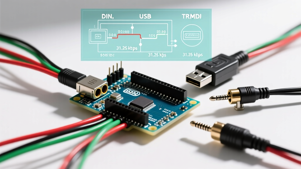
In 2026, the maker ecosystem supports three primary physical layers for MIDI: the legacy 5-pin DIN, the ubiquitous USB connection, and the compact 3.5mm TRS (Tip-Ring-Sleeve) jack. This guide breaks down the electrical engineering principles, wiring topologies, and microcontroller selection criteria required to build a robust, jitter-free MIDI interface.
The Anatomy of MIDI: Serial Communication at 31,250 Baud
Before wiring any pins, you must understand the underlying protocol. MIDI 1.0 is an asynchronous serial protocol operating at exactly 31,250 bits per second (baud). The data frame consists of 1 start bit, 8 data bits, and 1 stop bit. Because musical timing is highly sensitive to latency, the microcontroller's hardware serial (UART) peripheral must be used; software-emulated serial (like SoftwareSerial) introduces unacceptable jitter and dropped notes.
Expert Insight: A common failure mode for beginners is attempting to use a baud rate of 38,400 (a standard serial rate) instead of 31,250. Even a 1% deviation in the microcontroller's clock crystal can cause MIDI receivers to reject the data stream. Always use hardware UART and configure it strictly to 31250 baud.
Three Ways to Build an Arduino MIDI Interface
1. The Classic 5-Pin DIN (Hardware Serial & Optocouplers)
The original MIDI specification relies on a 20mA current loop, not a standard voltage-based TTL serial signal. This design was chosen to prevent ground loops between interconnected audio equipment. To interface an Arduino's 5V or 3.3V TX pin with a 5-pin DIN connector, you must build an isolated driver circuit.
- DIN Pin 2: Ground (connected to the Arduino GND).
- DIN Pin 4: Current Source (connected to 5V via a 220Ω resistor).
- DIN Pin 5: Current Sink (connected to the Arduino TX pin via a 220Ω resistor).
For receiving MIDI (MIDI IN), the MIDI Association specifications mandate an optocoupler to maintain galvanic isolation. The 6N138 or PC900 optocouplers are industry standards. You must include a 1N4148 switching diode across the optocoupler's input pins (pins 2 and 3) in reverse bias to protect the internal LED from voltage spikes, and a 1kΩ pull-up resistor on the output side to interface with the Arduino's RX pin.
2. USB MIDI (Native vs. Emulated)
Modern DAWs (Digital Audio Workstations) and mobile devices prefer USB MIDI. However, not all Arduinos handle USB equally. Standard boards like the Arduino Uno R3 use an ATmega16U2 chip as a serial-to-USB bridge. To make it a MIDI interface, you must flash custom firmware (like the HIDUINO or MocoLUFA firmware) to trick the computer into recognizing it as a MIDI class device.
For a frictionless experience, use boards with native USB support, such as the Arduino Leonardo (ATmega32U4) or the Arduino Zero (SAMD21). These boards can utilize the official Arduino MIDIUSB library to send and receive MIDI packets natively without custom firmware flashing. In 2026, the Raspberry Pi Pico (RP2040) has also become a dominant force here, utilizing the TinyUSB stack to act as a highly reliable, low-cost USB MIDI interface.
3. TRS Type-A MIDI (The Modern Compact Standard)
Introduced by the MIDI Manufacturers Association (MMA) to save space on compact synthesizers, 3.5mm TRS MIDI carries the exact same electrical current loop as 5-pin DIN, but on a smaller jack. There are two competing wiring standards: Type-A and Type-B.
Wiring Warning: Type-A vs. Type-B
Type-A (KORG, Arturia, Make Noise): Tip = Pin 4 (Source), Ring = Pin 5 (Sink), Sleeve = Pin 2 (Ground).
Type-B (Novation, Akai): Tip = Pin 5 (Sink), Ring = Pin 4 (Source), Sleeve = Pin 2 (Ground).
Always verify the target synthesizer's TRS standard before wiring your Arduino output, or you risk shorting the current loop and damaging the microcontroller's UART pin.
Microcontroller Hardware Comparison Matrix
Choosing the right board dictates your interface's latency, polyphony, and ease of integration. Below is a comparison of popular MCUs for MIDI projects based on current 2026 market availability and pricing.
| Microcontroller | Native USB MIDI | Hardware UARTs | Approx. Price (USD) | Best Use Case |
|---|---|---|---|---|
| Arduino Leonardo (ATmega32U4) | Yes | 1 | $22.00 | Simple USB MIDI controllers |
| Teensy 4.0 (NXP i.MX RT1062) | Yes (High Speed) | 8 | $26.50 | Complex polyphonic synths, MIDI 2.0 |
| Raspberry Pi Pico (RP2040) | Yes (via TinyUSB) | 2 | $4.00 | Budget TRS/DIN interfaces |
| Arduino Uno R4 Minima (RA4M1) | Yes | 4 | $20.00 | Modern DIN/USB hybrid builds |
For advanced users exploring the new MIDI 2.0 specification—which introduces 32-bit resolution, property exchange, and Universal MIDI Packets (UMP)—the Teensy 4.0 and 4.1 boards remain the gold standard due to their massive processing overhead and native USB high-speed capabilities.
Critical Failure Modes and Troubleshooting
Even with perfect code, hardware-level electrical issues can cause 'stuck notes' or phantom triggers. Here are the most common edge cases:
- Ground Loops in DIN Connections: If you bypass the optocoupler on the MIDI IN circuit and connect the Arduino ground directly to the incoming MIDI cable ground, you will create a ground loop. This manifests as a loud 60Hz hum in connected audio gear and can fry the UART pin if a voltage spike occurs. Solution: Never skip the optocoupler on MIDI IN.
- Optocoupler CTR Degradation: The Current Transfer Ratio (CTR) of optocouplers like the 6N138 degrades over time and varies by temperature. If your MIDI IN circuit works on the bench but fails in a hot venue, the CTR has likely dropped below the threshold needed to pull the RX pin low. Solution: Use a high-speed logic gate optocoupler like the H11L1, which has a much sharper switching threshold.
- USB Polling Rate Jitter: Standard USB Full-Speed (12 Mbps) devices are polled every 1ms. For tight drum sequencing, this 1ms jitter is audible. Solution: Use a High-Speed USB MCU (480 Mbps) like the Teensy 4.0, which reduces polling intervals to 125µs.
Practical Implementation: Sending a Note-On Message
When using a native USB board with the MIDIUSB library, sending a Note-On command requires packing the data into a 4-byte USB-MIDI event packet. The first byte defines the cable number and command type, while the remaining three bytes hold the standard MIDI status, note number, and velocity.
#include 'MIDIUSB.h'

void sendNoteOn(byte channel, byte pitch, byte velocity) {
  // 0x09 = Note-On, Cable 0
  midiEventPacket_t noteOn = {0x09, 0x90 | channel, pitch, velocity};
  MidiUSB.sendMIDI(noteOn);
  MidiUSB.flush();
}

void setup() {
  // No serial baud rate setup required for native USB MIDI
}

void loop() {
  sendNoteOn(0, 60, 127); // Middle C, Max Velocity
  delay(500);
  // Remember to send Note-Off (0x08) to prevent stuck notes!
}
Summary
Building a reliable Arduino MIDI interface bridges the gap between raw embedded systems programming and creative musical expression. By respecting the 31,250 baud hardware serial requirement, implementing proper galvanic isolation via optocouplers for DIN and TRS connections, and selecting a microcontroller with native USB descriptors, you can create professional-grade MIDI tools that rival commercial interfaces costing hundreds of dollars more.