
The 40-Pin Header: Anatomy of a Maker's Canvas
For over a decade, the 40-pin header has been the undisputed bridge between the digital logic of the Raspberry Pi and the physical world of sensors, motors, and relays. Whether you are migrating a legacy project from a Pi 3 to a Pi 4, or designing a custom HAT for the latest Pi 5, understanding the gpio pin layout raspberry pi ecosystem is non-negotiable for hardware makers. This community-driven resource cuts through the official documentation to highlight real-world quirks, architectural shifts, and the practical pitfalls we encounter on the workbench.
Power Rails: The 3.3V vs 5V Divide
The most common way community members destroy a Raspberry Pi SoC is by misunderstanding the power rails. The 40-pin header contains both 5V and 3.3V pins, but they are not interchangeable.
- 5V Pins (Physical 2, 4): Tied directly to the 5V USB-C power input. These are excellent for powering external 5V sensors, relay modules, or LED strips. However, they are unregulated; if your USB-C power supply sags under load, these pins will sag too.
- 3.3V Pins (Physical 1, 17): Generated by the onboard voltage regulator. On older models (Pi 1/2/3), this rail was limited to a meager 50mA. On the Pi 4 and Pi 5, the 3.3V supply is significantly more robust, but you must still respect the per-pin current limits.
Community Warning: Never backfeed 5V into a 3.3V GPIO pin (like BCM 2 or BCM 3). The Pi's internal logic operates strictly at 3.3V. Injecting 5V will bypass the protection diodes and instantly fry the ARM core or the RP1 southbridge.
Decoding the Matrix: BCM vs. BOARD Numbering
When writing Python scripts using libraries like RPi.GPIO or gpiozero, you will immediately face the numbering dilemma. The physical gpio pin layout raspberry pi header has 40 pins, but only 26 of them are programmable GPIOs. How you address them depends on your framework.
Maker Consensus: Always default to BCM (Broadcom SOC channel) numbering. It aligns with the official Raspberry Pi documentation, the
gpiozerolibrary defaults, and the silkscreen labels found on most modern third-party HATs. BOARD numbering (physical pin 1-40) is largely considered a legacy crutch that causes confusion when porting code between different Pi models.
For example, Physical Pin 11 is BCM 17. Physical Pin 12 is BCM 18 (the only pin with hardware PWM0). If you are using the gpiozero library, BCM is the native language of the API.
Dedicated Protocol Pins: I2C, SPI, and UART Mappings
While any GPIO can be bit-banged to simulate a protocol, the Pi features dedicated hardware interfaces mapped to specific pins. Knowing these by heart saves hours of debugging when configuring device tree overlays in /boot/firmware/config.txt.
| Protocol | Function | BCM GPIO | Physical Pin | Community Notes |
|---|---|---|---|---|
| I2C1 | SDA1 / SCL1 | 2 / 3 | 3 / 5 | Features onboard 1.8kΩ pull-up resistors to 3.3V. Do not add external pull-ups unless calculating parallel resistance. |
| SPI0 | MOSI / MISO / SCLK | 10 / 9 / 11 | 19 / 21 / 23 | CE0 (BCM 8) and CE1 (BCM 7) are active-low chip selects. Requires dtparam=spi=on. |
| UART0 | TXD / RXD | 14 / 15 | 8 / 10 | Often hijacked by the Bluetooth module on Pi 3/4. Use enable_uart=1 and dtoverlay=disable-bt to reclaim for serial consoles. |
| PWM0 | Hardware PWM | 18 | 12 | The only pin with true, stable hardware PWM without DMA jitter. Essential for servo control. |
The Raspberry Pi 5 Paradigm Shift: Enter the RP1
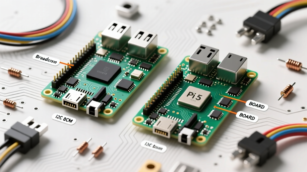
If you are reading older forum posts about the gpio pin layout raspberry pi, be aware that the Pi 5 introduced a massive architectural change. The BCM2711 SoC no longer handles the GPIO header directly. Instead, Raspberry Pi designed a custom southbridge chip called the RP1.
How RP1 Changes the Game
The RP1 handles all peripheral I/O, including the 40-pin header, Ethernet, and USB. From a wiring perspective, the physical layout remains 100% backward compatible with the Pi 4. However, the underlying electrical characteristics and software tooling have shifted. The RP1 operates on a PCIe Gen 2 link to the main BCM2712 processor. This means GPIO interrupts and state changes are now routed over PCIe, which slightly alters latency profiles for high-speed bit-banging compared to the Pi 4's direct memory-mapped GPIO.
Furthermore, the Pi 5 introduces new headers outside the standard 40-pin layout, including a PCIe Gen 2 FPC connector and a dedicated RTC battery header (J5), expanding the definition of the Pi's physical I/O canvas.
Real-World Troubleshooting: Fried Pins and Pull-Up Resistors
Even experienced makers occasionally wire a circuit backward or forget a common ground. Here is how the community diagnoses GPIO health and signal integrity issues.
Using pinctrl for Diagnostics
On Raspberry Pi OS Bookworm (and specifically on the Pi 5), the legacy raspi-gpio tool has been deprecated. The new standard for inspecting the gpio pin layout raspberry pi state via the command line is pinctrl.
If you suspect a pin is dead or stuck in an alternate function, open your terminal and run:
pinctrl getThis will dump the current state, direction (ip/op), and pull-up/pull-down status of every RP1/BCM pin. If a pin reads lo when it should be floating, or if it shows an alternate function (like a0 for SPI) when you expect standard GPIO, you know the issue is software configuration, not a fried trace.
The I2C Bus Lockup Phenomenon
A frequent community support ticket involves the I2C bus (BCM 2 and 3) locking up and returning a Remote I/O error in Python. This rarely means the pins are dead. Because these pins have 1.8kΩ onboard pull-ups, connecting a 5V Arduino or an unlevel-shifted sensor can cause voltage contention. If the SDA line gets pulled low while the Pi is expecting a clock cycle, the Linux I2C kernel driver will hang the bus to prevent data corruption.
The Fix: Always use a bidirectional logic level converter (like the BSS138 MOSFET circuit) when bridging Pi I2C to 5V networks, and ensure your external devices do not have their own pull-up resistors enabled, which would parallel with the Pi's internal 1.8kΩ resistors and pull the voltage out of spec.
Essential Community Tools for Pin Verification
Before soldering or crimping Dupont connectors, verify your mappings. The undisputed champion of visual reference is Pinout.xyz. It provides an interactive, color-coded map of the header, including the hidden EEPROM ID pins (BCM 0 and 1) used for HAT auto-configuration.
Additionally, always consult the Official Raspberry Pi GPIO Documentation when dealing with device tree overlays. The intersection of physical wiring and software overlay configuration is where 90% of maker bugs originate. By respecting the electrical limits of the 3.3V rail, understanding the RP1 architecture, and utilizing modern diagnostic tools like pinctrl, you can ensure your hardware projects survive their first boot and thrive in production.