
The 'PMW Arduino' Phenomenon: Why Precision PWM Matters
If you have landed here searching for 'pmw arduino', you are not alone. 'PMW' is consistently one of the most common typographical errors in the maker space for Pulse Width Modulation (PWM). But whether you call it PMW or PWM, the physics of duty cycles, switching frequencies, and inductive loads remain exactly the same. In 2026, as the Arduino ecosystem expands beyond the classic 8-bit ATmega328P to include 32-bit ARM Cortex-M4 architectures like the Renesas RA4M1, mastering hardware timers is more critical than ever.
Standard analogWrite() functions are great for dimming an LED, but they fall apart when you need ultrasonic motor control, high-frequency switching power supplies, or precise phase-shifted signals. This community resource roundup synthesizes the best open-source libraries, register-level hacks, and hardware interfacing techniques curated by the electrical engineering and maker communities.
Hardware Showdown: Classic ATmega328P vs. Uno R4 Minima
Before diving into software, we must understand the silicon. The transition from the Arduino Uno R3 to the Arduino Uno R4 Minima fundamentally changed how we handle PWM. The R4 utilizes the Renesas RA4M1 microcontroller, featuring advanced General PWM Timers (GPT) that dwarf the capabilities of the legacy 8-bit timers.
| Feature | Uno R3 (ATmega328P) | Uno R4 Minima (RA4M1) |
|---|---|---|
| MCU Core | 8-bit AVR | 32-bit ARM Cortex-M4 |
| Clock Speed | 16 MHz | 48 MHz |
| PWM Resolution | 8-bit (Default) | Up to 32-bit (GPT) |
| Default Freq (Timer1) | 490.20 Hz | 490 Hz (Mapped for compatibility) |
| Max Achievable Freq | ~62.5 kHz (8-bit mode) | ~24 MHz (High-speed modes) |
| Audio Interference | High (Audible Whine) | Low (Easily pushed >20kHz) |
Top Community Libraries for Advanced PWM Control
When the native Arduino analogWrite Reference hits its limits, the community steps in. Here are the most reliable libraries for advanced PWM manipulation in 2026.
1. TimerOne & TimerThree (The Classics)
Maintained originally by Paul Stoffregen, the TimerOne library remains the gold standard for ATmega328P and ATmega2560 boards. It allows you to configure the 16-bit Timer1 to generate precise interrupts and PWM signals simultaneously.
- Best For: Generating precise 20kHz ultrasonic signals for DC motor control to eliminate audible whine.
- Limitation: Strictly tied to AVR architecture; will not compile on ARM-based boards like the R4 or Due.
2. PWM.h by Terry Myers (The Frequency Master)
The PWM.h library is a powerhouse for AVR boards. Unlike TimerOne, it allows you to change the PWM frequency on any timer, including the 8-bit Timer0 and Timer2, without completely breaking the Arduino core timing functions (though it requires careful recalculation of millis()).
- Best For: Synchronizing multiple PWM channels and setting exact custom frequencies across different timer blocks.
3. Arduino_GPT (For Uno R4 / Renesas)
For the newer RA4M1 architecture, community developers have wrapped the complex Renesas Hardware Manual register configurations into the Arduino_GPT library. This allows access to the dead-time insertion features crucial for H-bridge motor drivers.
Register-Level Hacking: Changing Prescalers on AVR
For those who prefer bare-metal programming over heavy libraries, manipulating the Timer/Counter Control Registers (TCCR) directly is the most efficient method. Let us look at how to push Timer1 on the ATmega328P into the ultrasonic range to eliminate DC motor whine.
By default, Timer1 uses a prescaler of 64. The math for the PWM frequency in Phase Correct mode is:
Frequency = Clock_Speed / (Prescaler * 510)
16,000,000 / (64 * 510) = 490.20 Hz
To push this above human hearing (20,000 Hz), we change the prescaler to 1. As detailed in Nick Gammon's Timer Guide, we use bitwise operations to clear the prescaler bits and set them to 0x01:
// Clear prescaler bits on Timer1
TCCR1B = TCCR1B & B11111000;
// Set prescaler to 1 (No prescaling)
TCCR1B = TCCR1B | B00000001;
The Result: 16,000,000 / (1 * 510) = 31,372 Hz. Your motor will now run silently, and your analogWrite(9, value) commands will still work perfectly, just at a much higher switching frequency.
Real-World Hardware Interfacing: Beyond the Logic Pin
Generating the PWM signal is only 20% of the battle; switching the load is the other 80%. A common failure mode in community projects is connecting high-current loads directly to MCU pins or using the wrong MOSFETs.
The Logic-Level MOSFET Rule
Never use a standard MOSFET like the IRF520 for 5V Arduino PWM. The IRF520 requires 10V on the gate to fully turn on (RDS(on) is rated at VGS = 10V). At 5V, it operates in its linear region, acting as a resistor, overheating, and failing. Instead, use logic-level MOSFETs like the IRLZ44N or STP16NF06L, which guarantee full enhancement at VGS = 4.5V or 5V.
Gate Drive Circuitry
- Gate Resistor (100Ω - 220Ω): Place this in series between the Arduino PWM pin and the MOSFET gate. It limits the inrush current required to charge the gate capacitance, protecting the MCU's internal IO pin from overcurrent damage.
- Pull-Down Resistor (10kΩ): Connect this between the gate and ground. During MCU boot-up, IO pins float. This resistor ensures the MOSFET stays firmly OFF until the Arduino initializes the pin as an OUTPUT.
- Flyback Diode (1N5819 or SS34): Mandatory across inductive loads (motors, solenoids). Schottky diodes are preferred over standard 1N4007s due to their faster reverse recovery times, which handle high-frequency PWM edges much better.
Troubleshooting Common PWM Artifacts
Camera Flicker: If your PWM-driven LED strips flicker on smartphone cameras but look fine to the naked eye, your frequency is clashing with the camera's rolling shutter. Push the PWM frequency above 2,000 Hz using the register hacks above to eliminate banding on video.
Ground Bounce and EMI
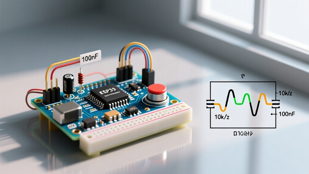
High-frequency PWM switching creates massive di/dt (change in current over time) spikes. If you share a thin ground wire between your high-power motor ground and your Arduino ground, the voltage spikes will reset your microcontroller. Always use a star-ground topology, and place a 100nF ceramic capacitor in parallel with a 100µF electrolytic capacitor directly at the MOSFET source and load ground to absorb high-frequency EMI.
Frequently Asked Questions (FAQ)
Can I use PWM to simulate a true analog DAC output?
Yes, but it requires an RC low-pass filter. By passing the PWM signal through a resistor (e.g., 4.7kΩ) and a capacitor (e.g., 10µF) to ground, you smooth the square wave into a DC voltage. The cutoff frequency of the filter must be at least 10 times lower than your PWM frequency to minimize ripple.
Why does my servo jitter when using PWM?
Servos expect a very specific 50 Hz signal with a pulse width between 1000µs and 2000µs. Standard analogWrite() outputs ~490 Hz, which will cause severe jitter or damage the servo's internal potentiometer feedback loop. Always use the dedicated Servo.h library or configure a timer specifically for 50 Hz.
Does changing Timer0 PWM frequency break my code?
Yes. Timer0 handles the Arduino core timing functions, including delay(), millis(), and micros(). If you alter Timer0's prescaler to change the PWM frequency on pins 5 or 6, your time-based functions will run at the wrong speed. Stick to modifying Timer1 (pins 9, 10) or Timer2 (pins 3, 11) for safe experimentation.