
The Engineering Reality of Arduino RPM Measurement
Building a reliable tachometer with Arduino is a classic embedded systems project, but most online tutorials fail when exposed to real-world electric motors. They rely on blocking delay() functions, polling loops that miss pulses at high speeds, and ignore the massive electromagnetic interference (EMI) generated by brushed and brushless DC motors. In 2026, with the widespread availability of high-speed microcontrollers like the Arduino Uno R4 Minima and advanced Hall-effect ICs, there is no excuse for inaccurate RPM readings.
This configuration guide bypasses the beginner traps. We will design a robust, interrupt-driven tachometer using period-based pulse measurement, hardware EMI filtering, and safe unsigned-integer math to guarantee accuracy from 10 RPM up to 50,000 RPM.
Sensor Selection Matrix: Hall Effect vs. Optical
The foundation of any tachometer is the transducer. While optical sensors are common in hobbyist kits, they are notoriously fragile in industrial or automotive environments. Below is a technical comparison of the three most viable sensor architectures for MCU-based tachometry.
| Sensor Type / Model | Typical Cost (2026) | Max Frequency | Environmental Robustness | Best Application |
|---|---|---|---|---|
| A3144 Hall Effect (Discrete) | $0.45 - $0.80 | 10 kHz | High (Immune to dust/oil) | Dirty environments, automotive crankshafts |
| KY-003 IR Optical Module | $1.50 - $3.00 | 20 kHz | Low (Fails in sunlight/dust) | Clean benchtop testing, 3D printer encoders |
| AS5600 Magnetic Encoder (I2C) | $3.50 - $5.50 | I2C Bus Limit | Medium (Requires precise alignment) | PID motor control, robotics, high-precision positioning |
Configuration Decision: For a general-purpose, high-reliability tachometer, the A3144 Hall Effect sensor paired with a neodymium magnet mounted on the rotating shaft is the optimal choice. It requires no optical line-of-sight and operates flawlessly through dust, grease, and ambient light.
Hardware Configuration and EMI Mitigation
The most common failure mode when pairing a tachometer with Arduino is phantom interrupts caused by motor EMI. The high-frequency voltage spikes from motor commutation couple into the sensor's signal wire, tricking the microcontroller into registering thousands of extra pulses.
The Bill of Materials (BOM)
- Microcontroller: Arduino Uno R4 Minima ($20.00) or Arduino Nano Every ($14.50). Both feature excellent 5V logic thresholds and dedicated hardware interrupt pins.
- Sensor: A3144 Hall Effect IC or a pre-built KY-024 Hall module.
- Filtering Components: 10kΩ pull-up resistor, 1kΩ series resistor, 10nF ceramic capacitor (X7R dielectric), and a 0.1µF decoupling capacitor.
- Target: N52 grade Neodymium magnet (6mm x 2.5mm).
Wiring and Hardware Low-Pass Filter
Do not connect the Hall sensor output directly to the Arduino pin. You must condition the signal. Follow this exact wiring topology:
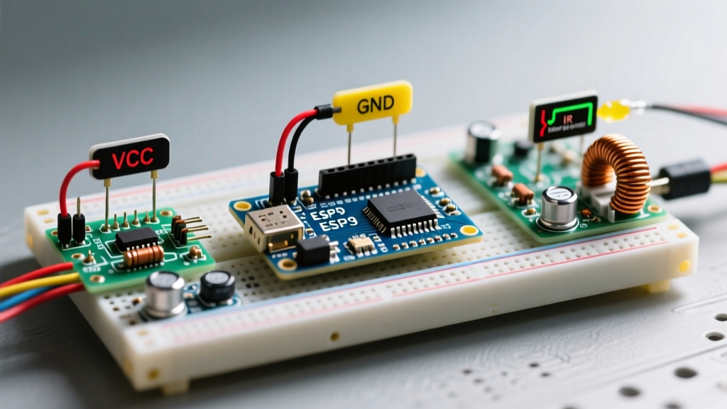
- Power Delivery: Connect the A3144 VCC to the Arduino 5V pin and GND to GND. Place the 0.1µF decoupling capacitor as close to the sensor legs as physically possible to suppress local high-frequency noise.
- Pull-Up: The A3144 features an open-collector output. Connect a 10kΩ resistor between the 5V rail and the sensor's OUT pin.
- RC Low-Pass Filter: To eliminate EMI spikes, route the sensor's OUT pin through a 1kΩ series resistor to Arduino Pin 2 (INT0). Connect a 10nF capacitor from Pin 2 to GND. This creates a hardware low-pass filter with a cutoff frequency of roughly 15.9 kHz, allowing valid RPM pulses through while shorting high-frequency EMI spikes to ground.
Expert Insight: Never rely solely on software debouncing for high-speed tachometry. By the time the software realizes a pulse is noise, the interrupt service routine (ISR) has already wasted precious CPU cycles. Hardware RC filtering is mandatory for motors exceeding 5,000 RPM.
The Mathematics of Pulse-to-RPM Conversion
Beginners often count the number of pulses over a fixed one-second window (frequency measurement). This approach is terrible for low RPMs (resulting in massive quantization errors) and introduces a mandatory one-second latency into your control loop.
Instead, we use Period Measurement. We measure the exact time elapsed between consecutive pulses using the Arduino's micros() function.
The RPM Formula
If your shaft has one magnet (one pulse per revolution), the math is straightforward:
RPM = 60,000,000 / (pulse_interval_microseconds)
If you are using a gear with multiple teeth or multiple magnets (Pulses Per Revolution, or PPR), the formula adjusts to:
RPM = 60,000,000 / (pulse_interval_microseconds * PPR)
Example: A motor with a 4-tooth encoder gear spinning at 3,000 RPM generates 200 pulses per second. The time between pulses is 5,000 µs. 60,000,000 / (5000 * 4) = 3,000 RPM.
Firmware: Configuring Hardware Interrupts
To capture high-speed pulses without blocking the main loop, we must configure hardware interrupts. According to the Arduino attachInterrupt() Reference, Pin 2 on standard AVR and Renesas-based Arduino boards maps to INT0, which is ideal for edge-triggered timing.
Variable Scoping and the Volatile Keyword
Variables shared between the ISR and the main loop() must be declared with the volatile keyword. As detailed in the Arduino volatile Qualifier Documentation, this instructs the compiler to always read the variable from RAM rather than caching it in a CPU register, preventing severe synchronization bugs.
Handling the micros() Overflow Edge Case
The micros() function overflows and resets to zero approximately every 70 minutes. If an overflow occurs exactly between two pulses, a naive subtraction (current_time - previous_time) will yield a massive negative number, resulting in an RPM calculation in the millions.
The Fix: Always use unsigned long for timing variables. In C/C++, subtracting a larger unsigned integer from a smaller one (due to rollover) naturally wraps around and yields the correct positive time delta. Do not use int or long for timing math.
Interrupt Service Routine (ISR) Architecture
Your ISR must be as lightweight as possible. Do not perform floating-point math, serial printing, or complex logic inside the ISR.
- Step 1: Read
micros()and store it in a local variable. - Step 2: Subtract the previous timestamp to find the delta.
- Step 3: Save the delta to a
volatile unsigned longglobal variable. - Step 4: Update the previous timestamp.
- Step 5: Exit the ISR immediately.
The main loop() will then read this global delta variable, perform the RPM division, and handle Serial output or LCD updates.
Troubleshooting Matrix: Edge Cases and Signal Noise
Even with perfect code, physical realities can disrupt your tachometer. Use this diagnostic matrix to resolve common field issues.
| Symptom | Probable Cause | Engineering Solution |
|---|---|---|
| RPM reads exactly double the actual speed. | Interrupt triggering on both RISING and FALLING edges. | Change attachInterrupt mode to FALLING or RISING only. |
| RPM spikes to maximum randomly when motor starts. | Motor brush EMI coupling into the signal wire. | Verify the 1kΩ/10nF RC hardware filter. Add a Schmitt Trigger IC (74HC14) for severe noise. |
| RPM drops to zero intermittently at high speeds. | Magnet passing too fast for sensor latch time, or gap is too wide. | Reduce the air gap between the A3144 and magnet to < 3mm. Ensure the magnet is oriented with the correct pole facing the sensor's branded side. |
| Serial monitor prints garbled text or freezes. | ISR is taking too long, starving the Serial buffer. | Move all Serial.print() functions out of the ISR. Use a boolean flag to trigger printing in the main loop. |
Scaling Up: Multi-Cylinder and High-PPR Configurations
When adapting this tachometer architecture for complex machinery, such as a 4-cylinder combustion engine or a CNC spindle with a 60-tooth encoder wheel, the pulse frequency can exceed 10 kHz. At these frequencies, the Arduino's ISR overhead (roughly 5-8 microseconds per trigger) becomes a significant factor.
If you are measuring a 60-tooth wheel at 20,000 RPM, you are generating 20,000 pulses per second. The time between pulses is just 50 µs. The ISR will consume nearly 20% of the microcontroller's total processing time. In these extreme 2026 use cases, consider upgrading to an Arduino Portenta H7 or utilizing the Uno R4's built-in Timer Capture hardware peripherals, which can record pulse timestamps at the silicon level without CPU intervention.
Final Calibration and Verification
Before deploying your tachometer in a production or safety-critical environment, calibrate it against a known reference. A commercial optical laser tachometer (such as the Extech 461920, typically priced around $65) serves as an excellent baseline. Compare the Arduino's Serial output against the laser tachometer at 10%, 50%, and 90% of the motor's maximum rated speed. If a linear offset exists, apply a software correction multiplier in your main loop's RPM calculation.
By respecting hardware physics, implementing proper RC filtering, and utilizing safe unsigned integer math, your Arduino-based tachometer will deliver industrial-grade reliability far beyond standard hobbyist implementations.
For further reading on magnetic sensor integration, review the Texas Instruments Hall-Effect Sensor Portfolio documentation, which provides excellent application notes on air-gap tolerances and magnetic hysteresis.